


Hf Low-Power Cw Transmitter
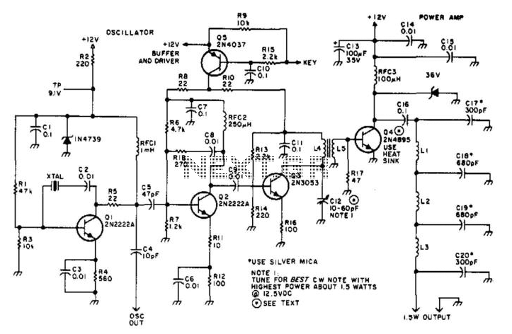
Description: Suitable for amateur use, this 1.5-W transmitter operates on a 12-V supply. Q1 functions as an oscillator utilizing a surplus FT243 crystal. Q2 serves as a buffer driver and is activated through the keying transistor Q5. Q3 acts as a driver for Q4, which requires a heatsink. Q4 generates approximately 1.5 W of output power. Coil specifications are provided in the parts list. C12 is tuned for optimal power output.
This 1.5-W transmitter circuit is designed for amateur radio operators, offering a compact and efficient solution for low-power transmission. The circuit operates from a 12-V power supply, making it suitable for various applications. The oscillator stage, represented by transistor Q1, utilizes an FT243 crystal for frequency stability, ensuring reliable performance within amateur bands.
Transistor Q2 functions as a buffer driver, providing impedance matching between the oscillator and the subsequent stages of the circuit. The keying mechanism is implemented through transistor Q5, which allows for on/off control of the transmitter, enabling operators to transmit signals as needed without affecting the oscillator's performance.
Transistor Q3 is employed as a driver for the final output stage, Q4, which is responsible for amplifying the signal to the desired output power level. It is crucial to attach a heatsink to Q4 to dissipate heat generated during operation, thus preventing thermal damage and maintaining efficiency. The output power from Q4 is approximately 1.5 W, suitable for short-range communication.
Coil specifications are essential for tuning the transmitter to the desired frequency, and these details are available in the parts list accompanying the schematic. Capacitor C12 plays a critical role in fine-tuning the circuit for optimal power output, and it should be adjusted to achieve the best performance in terms of signal clarity and transmission range.
Overall, this transmitter circuit offers a practical solution for amateur radio enthusiasts looking to build a low-power transmitter with straightforward components and clear operational characteristics. Suitable for amateur use, this 1.5-W transmitter runs on a 12-V supply. Ql is an oscillator using a surplus FT2 43 crystal. Q2 is a buffer driver and is keyed via keying transistor Q5. Q3 acts as a driver for Q4 (which should be heatsinked). Q4 develops about 1.5-W output. Coil data is given in the parts list. C12 is adjusted for best power output.
This 1.5-W transmitter circuit is designed for amateur radio operators, offering a compact and efficient solution for low-power transmission. The circuit operates from a 12-V power supply, making it suitable for various applications. The oscillator stage, represented by transistor Q1, utilizes an FT243 crystal for frequency stability, ensuring reliable performance within amateur bands.
Transistor Q2 functions as a buffer driver, providing impedance matching between the oscillator and the subsequent stages of the circuit. The keying mechanism is implemented through transistor Q5, which allows for on/off control of the transmitter, enabling operators to transmit signals as needed without affecting the oscillator's performance.
Transistor Q3 is employed as a driver for the final output stage, Q4, which is responsible for amplifying the signal to the desired output power level. It is crucial to attach a heatsink to Q4 to dissipate heat generated during operation, thus preventing thermal damage and maintaining efficiency. The output power from Q4 is approximately 1.5 W, suitable for short-range communication.
Coil specifications are essential for tuning the transmitter to the desired frequency, and these details are available in the parts list accompanying the schematic. Capacitor C12 plays a critical role in fine-tuning the circuit for optimal power output, and it should be adjusted to achieve the best performance in terms of signal clarity and transmission range.
Overall, this transmitter circuit offers a practical solution for amateur radio enthusiasts looking to build a low-power transmitter with straightforward components and clear operational characteristics. Suitable for amateur use, this 1.5-W transmitter runs on a 12-V supply. Ql is an oscillator using a surplus FT2 43 crystal. Q2 is a buffer driver and is keyed via keying transistor Q5. Q3 acts as a driver for Q4 (which should be heatsinked). Q4 develops about 1.5-W output. Coil data is given in the parts list. C12 is adjusted for best power output.
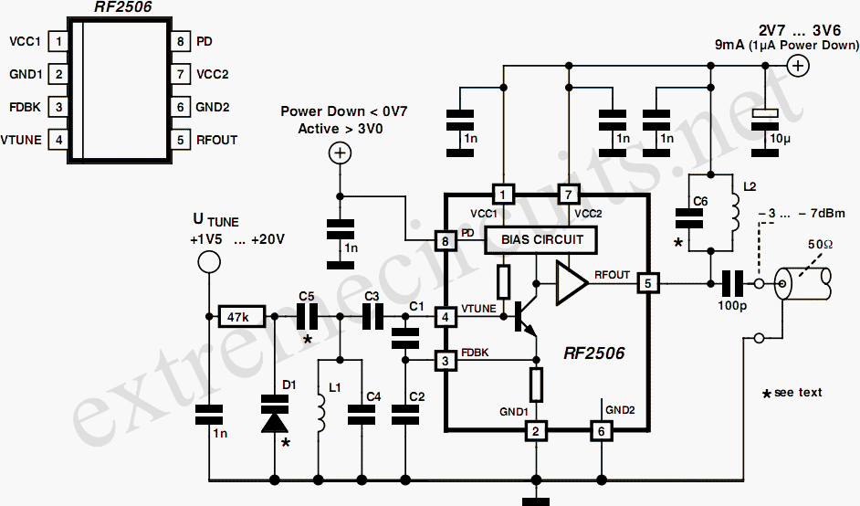
10 to 1000 MHz Oscillator circuit with RF2506
Today, it is no longer necessary to use discrete components for constructing oscillators. Many manufacturers now offer ready-made voltage-controlled oscillator (VCO) integrated circuits (ICs) that require only a few external components to determine the frequency. An example of such an...
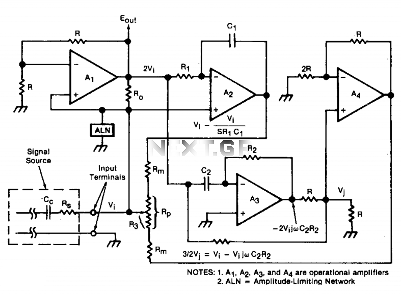
Wide frequency oscillator
An oscillator/amplifier is resistively tunable over a wide frequency range. Feedback circuits containing operational amplifiers, resistors, and capacitors synthesize the electrical effects of inductance and capacitance in parallel between the input terminals. The synthetic inductance and capacitance, and therefore the...
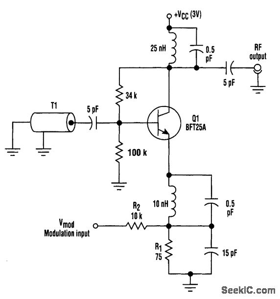
FM HF OSCILLATOR WITH NO VARACTOR
This circuit utilizes base-charging capacitance modulation instead of a varactor to frequency-modulate a high-frequency oscillator. This approach eliminates the significant voltage change required by a varactor, which can pose challenges in battery-powered systems with limited supply voltages. T1 serves as...
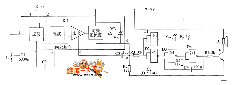
Metal detector circuit diagram 5
The metal detector circuit comprises an oscillator and a sound-light alarm circuit. The oscillator circuit includes an inductor (L), a capacitor (C1), a sensor switch integrated circuit (IC1) that integrates the oscillator, detector, comparator circuit, and peripheral components. The sound-light...
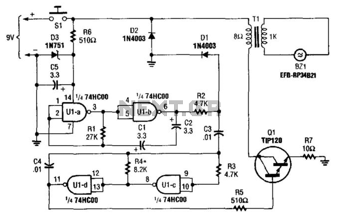
Sonic Defender
This oscillator-driver produces a loud sound of approximately 3 kHz, modulated with a 10-Hz warble. BZ1 is a Matsushita EFB-RP3. U1A generates the 10-Hz waveform that modulates the 3-kHz tone produced by U1C and U1D. Q1 drives the transducer through...
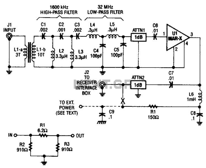
Hf Broadband Antenna Preamp Circuit
The HF/SW receiver preamplifier consists of a broadband toroidal transformer (LI-a and Ll-b), an LC network featuring a 1600-kHz high-pass filter and a 32-MHz low-pass filter, inductors L2 and L3 (26 turns of #26 enameled wire wound on an Amidon...

Local Oscillator For Double Balanced Mixers Circuit
This circuit includes an amplifier designed to deliver +10 dBm to an SBL series (Mini-Circuits) or a similar type of doubly-balanced mixer assembly. The circuit parameters are specified for 80 to 90 MHz crystals, although the values of the oscillator...
HF linear amplifier circuit
The power amplifier (PA) output Pi section features two variable capacitors: one ranging from 20 to 120 pF and a second, custom-built capacitor with a range of 50 to 450 pF. The latter is activated for lower frequency bands using...
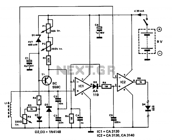
Metallic pipe detector
This circuit employs a 15-kHz oscillator coil. When metal is removed from the energy field, the oscillator voltage is rectified and compared to a reference. A decrease in oscillator voltage activates comparator IC2, causing D4 (LED) to turn off.
L1 consists...