


SCA broadcast receiver circuit diagram
#LM567
#SCA broadcast
#phase-locked loop
#demodulation
#receiver
#narrow-band
#radio
#broadcast
#frequency
#signal processing
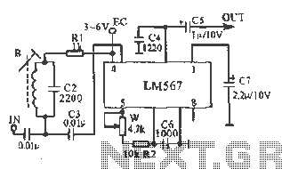
Description: This figure illustrates the schematic of the LM567 SCA broadcast reception information machine. The LM567 serves as a narrow-band phase-locked loop designed primarily for SCA broadcast demodulation. The configuration includes a potentiometer (W) and capacitor (C6) that determine the internal VCO center frequency of the integrated circuit (IC). The center frequency can be fine-tuned using the trimmer potentiometer (W). An enameled inductance coil (B) with a value of 0.088 is utilized, wound around a 10x10 mm IF-shaped core transformer with 360 turns, resulting in an inductance of 3mH. A resonant capacitor of 2200pF, made of ceramic material, is selected for optimal performance, while the potentiometer (W) can be used for fine-tuning resistance. No special requirements are imposed on the other components.
The LM567 SCA broadcast reception circuit is an efficient solution for demodulating SCA signals, utilizing the phase-locked loop (PLL) architecture to achieve a stable output. The LM567 integrates various functionalities, including a voltage-controlled oscillator (VCO) that can be adjusted to lock onto the desired frequency. The phase-locked loop works by comparing the phase of the input signal with that of the VCO, adjusting the frequency of the VCO until the two are in sync.
The choice of components is critical for the performance of the circuit. The potentiometer (W) allows for precise adjustments to the VCO frequency, accommodating variations in the input signal and ensuring optimal demodulation of the SCA broadcast. The capacitor (C6) plays a vital role in the stability and response time of the VCO, influencing the overall bandwidth of the demodulation process.
The inductance coil (B) is specifically designed to provide the required inductance value, which, in conjunction with the selected resonant capacitor, forms a tuned circuit that enhances signal reception. The 2200pF ceramic capacitor is chosen for its low equivalent series resistance (ESR) and stability over a range of temperatures, making it suitable for RF applications.
In summary, the LM567 SCA broadcast reception circuit is a well-structured design that leverages a combination of precise tuning elements and high-quality passive components to achieve effective demodulation of SCA signals, ensuring reliable performance in various broadcasting scenarios.This figure is converted into the manifold LM567 SCA broadcast reception information machine schematic. LM567 narrow-band phase-locked loop center to meet the basic role of SCA broadcast demodulation. R2 LM567 5,6,7 feet between the potentiometer W, C6 determine the IC internal VCO center frequency, the center frequency can be locked trimmer potentiometer W to adjust. Inductance coil B 0.088 enameled high strength available in 10X10 (mm) IF-shaped core transformer 360 laps around the inductance of 3mH, select the resonant capacitor 2200pF ceramic capacitor, W can be used to fine-tune the resistance, no special requirements other components.
The LM567 SCA broadcast reception circuit is an efficient solution for demodulating SCA signals, utilizing the phase-locked loop (PLL) architecture to achieve a stable output. The LM567 integrates various functionalities, including a voltage-controlled oscillator (VCO) that can be adjusted to lock onto the desired frequency. The phase-locked loop works by comparing the phase of the input signal with that of the VCO, adjusting the frequency of the VCO until the two are in sync.
The choice of components is critical for the performance of the circuit. The potentiometer (W) allows for precise adjustments to the VCO frequency, accommodating variations in the input signal and ensuring optimal demodulation of the SCA broadcast. The capacitor (C6) plays a vital role in the stability and response time of the VCO, influencing the overall bandwidth of the demodulation process.
The inductance coil (B) is specifically designed to provide the required inductance value, which, in conjunction with the selected resonant capacitor, forms a tuned circuit that enhances signal reception. The 2200pF ceramic capacitor is chosen for its low equivalent series resistance (ESR) and stability over a range of temperatures, making it suitable for RF applications.
In summary, the LM567 SCA broadcast reception circuit is a well-structured design that leverages a combination of precise tuning elements and high-quality passive components to achieve effective demodulation of SCA signals, ensuring reliable performance in various broadcasting scenarios.This figure is converted into the manifold LM567 SCA broadcast reception information machine schematic. LM567 narrow-band phase-locked loop center to meet the basic role of SCA broadcast demodulation. R2 LM567 5,6,7 feet between the potentiometer W, C6 determine the IC internal VCO center frequency, the center frequency can be locked trimmer potentiometer W to adjust. Inductance coil B 0.088 enameled high strength available in 10X10 (mm) IF-shaped core transformer 360 laps around the inductance of 3mH, select the resonant capacitor 2200pF ceramic capacitor, W can be used to fine-tune the resistance, no special requirements other components.
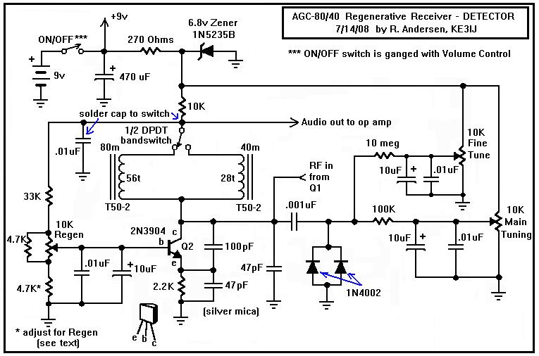
A Regenerative Receiver with AGC for 80 and 40 Meters
Here is a dual-band regenerative receiver that originated from encouraging communications with Jerry (K9UT) and another individual named Harvey, who constructed the original AGC-80 and its experimental successor, the AGC-80/30. Jerry has expressed his satisfaction with both receivers, noting their...
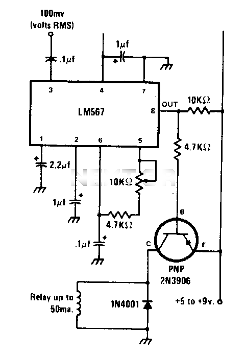
Tone-actuated relay
The circuit is designed using the LM567 tone decoder integrated circuit (IC), which operates with an input signal of approximately 100 millivolts at its designated frequency. The frequency can be adjusted using a 10 kΩ variable resistor, allowing it to...
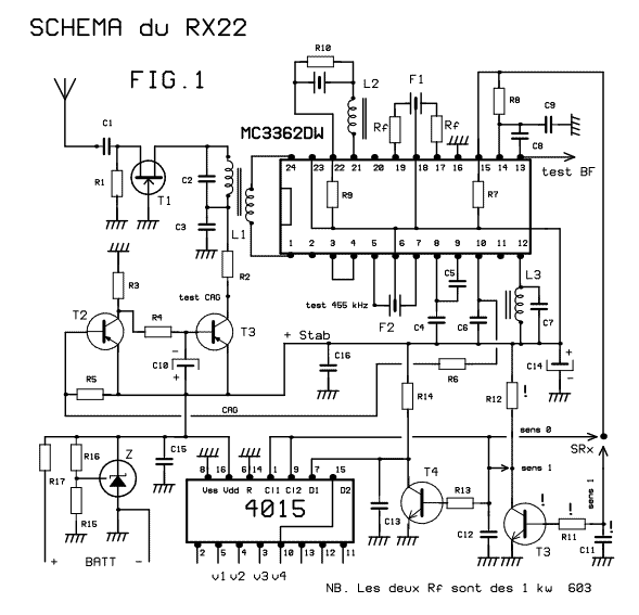
41-72MHz micro-receiver ( MC3362 )
This receiver weighs about 6 g, used in 41 and 72 MHz, met a great success with readers of the magazine. The RX22 is the subject of these lines is improved RX20. Adding a preamp-HF improving sensitivity. Establishment of an...
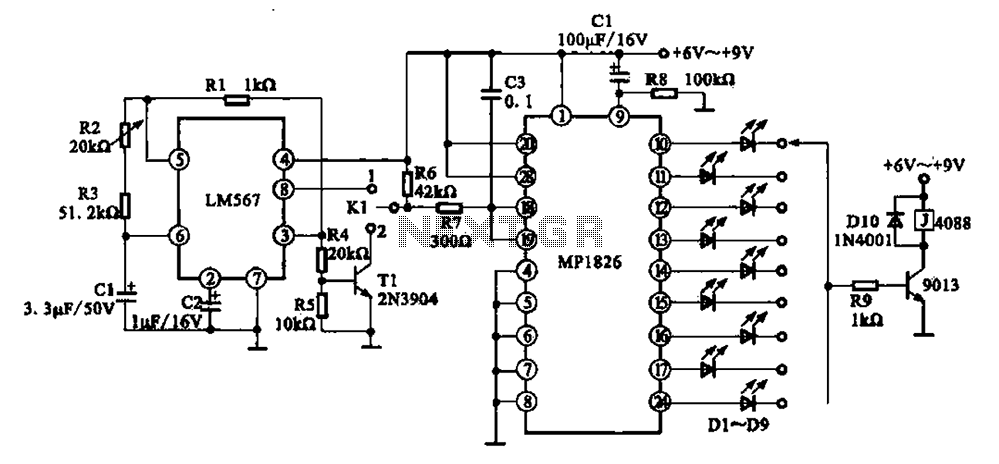
MP1826 by the LM567 and precision timer circuit
A precision circuit utilizing the LM567 timer, specifically the MPI826, where the LM567 functions as a dual-band oscillator. The MP1826 serves as a divider in the circuit, allowing the output signal from the LM567 to achieve extended timing. The oscillation...
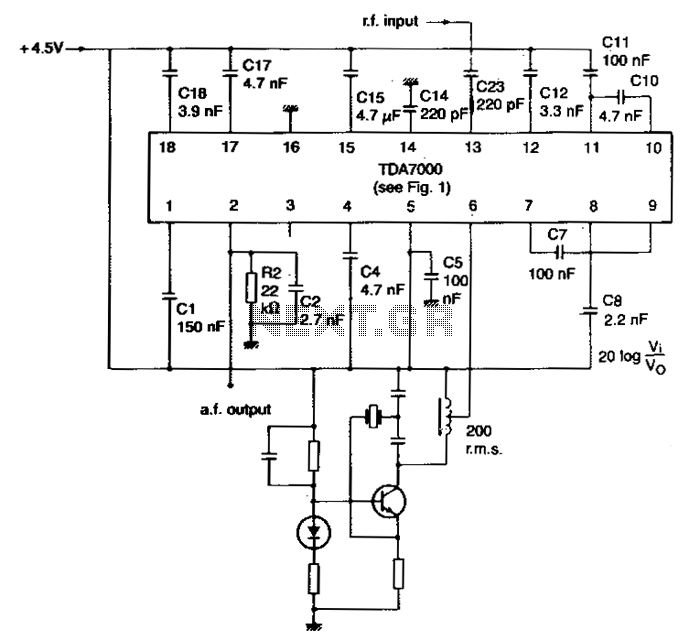
Narrow-band-fm-receiver
The local oscillator is controlled by a crystal, and the intermediate frequency (i-f) swing is minimally compressed. To prevent significant distortion of the demodulated audio signal, the deviation of the transmitted carrier frequency due to modulation must be limited. The...
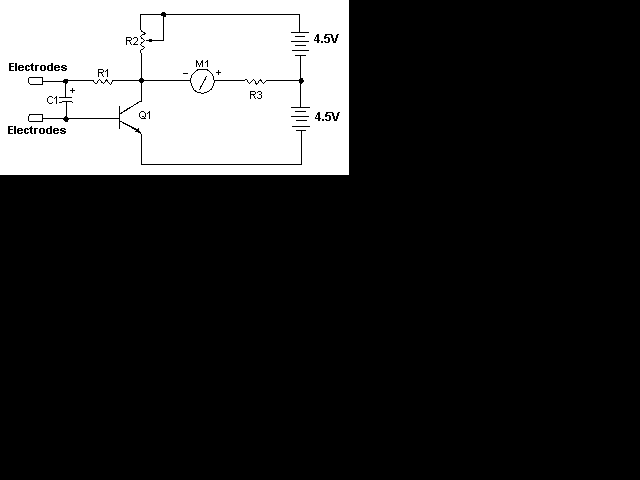
simple radio schematic
This page is provided to the domain owner free by Sedo's Domain Parking. Disclaimer: The domain owner and Sedo maintain no relationship with third-party advertisers. References to any specific service or trademark are not controlled by Sedo or the domain...
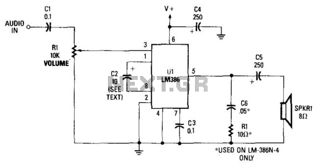
Receiver Audio Circuit
This simple receiver AF amplifier can supply several hundred milliwatts to an 8-ohm speaker. The gain is approximately 200X. If high gain is not required, C2 can be removed, resulting in a gain of 20. R1 and C6 are essential...
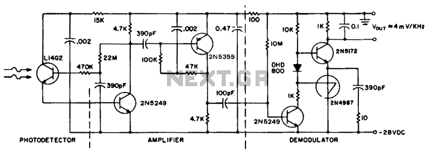
Receiver for 50 khz optical transmitter
To achieve maximum range, the receiver should be constructed similarly to a radio receiver front end, as the signals received will exhibit comparable frequency components and amplitudes of the photodiode current. The primary limitation on the receiver's performance is the...
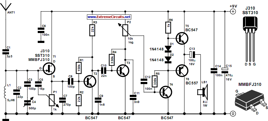
Tuned Radio Frequency (TRF) Receiver
Superheterodyne receivers have been mass-produced since around 1924, but for reasons of cost did not become successful until the 1930s.
Superheterodyne receivers represent a pivotal advancement in radio technology, characterized by their ability to convert high-frequency signals into lower intermediate...