


UHF TV Antenna Booster
#UHF
#antenna booster
#BF180 transistor
#band pass filter
#TV signal
#15dB gain
#low cost
#easy build
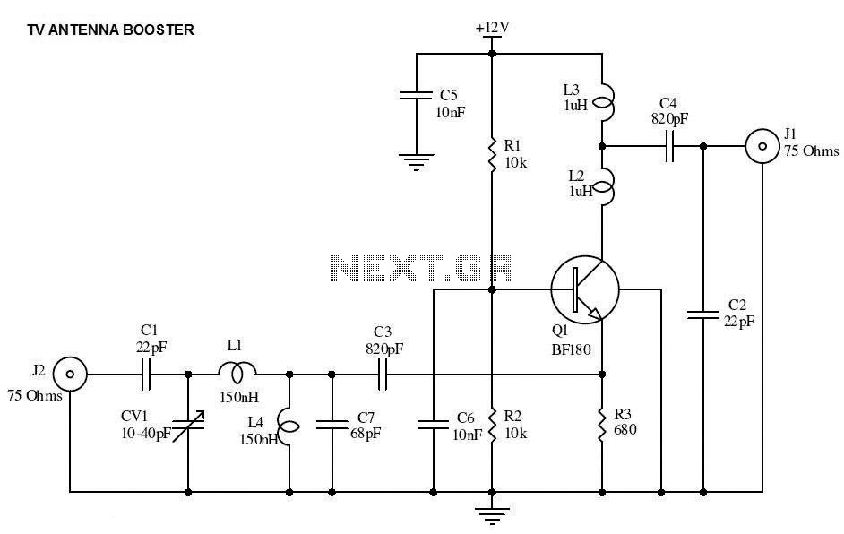
Description: This is the circuit diagram of a UHF band TV antenna booster with a 15dB gain power. This low-cost antenna booster is simple and easy to build. This circuit is based on the BF180 UHF transistor. The first stage is a band-pass filter constructed...
The UHF band TV antenna booster circuit is designed to amplify weak signals received by UHF antennas, thereby improving the overall quality of the television reception. The circuit utilizes the BF180 transistor, which is known for its high-frequency performance and low noise characteristics, making it suitable for applications in UHF amplification.
The circuit begins with a band-pass filter, which is crucial for eliminating unwanted frequencies while allowing the desired UHF signals to pass through. This filter is typically composed of inductors and capacitors arranged in a configuration that sets the cutoff frequencies. The design of the filter is essential, as it directly influences the performance of the booster by determining the bandwidth and selectivity of the signals being amplified.
Following the band-pass filter, the BF180 transistor is configured in a common-emitter arrangement to provide voltage gain. The transistor is biased correctly to operate in its active region, ensuring linear amplification of the incoming signal. The gain of 15dB indicates that the output signal will be significantly stronger than the input, which is beneficial for overcoming losses that may occur due to cable connections or other environmental factors.
Power supply considerations are also crucial in this circuit. A stable DC voltage is required to power the transistor, and capacitors may be used to filter out any noise from the power supply, ensuring that the amplifier operates efficiently and without distortion.
Overall, this UHF band TV antenna booster circuit is an effective solution for enhancing television signal reception in areas where signal strength is weak, and its simplicity makes it accessible for hobbyists and professionals alike. Proper assembly and component selection will ensure that the circuit performs optimally, delivering improved signal clarity and quality for UHF television broadcasts.This is the circuit diagram of UHF band TV antenna booster with 15dB gain power. This low cost antenna booster is simple and easy to build. This circuit formed based on BF180 UHF Transistor. The first stage is an band pass filter constructe..
The UHF band TV antenna booster circuit is designed to amplify weak signals received by UHF antennas, thereby improving the overall quality of the television reception. The circuit utilizes the BF180 transistor, which is known for its high-frequency performance and low noise characteristics, making it suitable for applications in UHF amplification.
The circuit begins with a band-pass filter, which is crucial for eliminating unwanted frequencies while allowing the desired UHF signals to pass through. This filter is typically composed of inductors and capacitors arranged in a configuration that sets the cutoff frequencies. The design of the filter is essential, as it directly influences the performance of the booster by determining the bandwidth and selectivity of the signals being amplified.
Following the band-pass filter, the BF180 transistor is configured in a common-emitter arrangement to provide voltage gain. The transistor is biased correctly to operate in its active region, ensuring linear amplification of the incoming signal. The gain of 15dB indicates that the output signal will be significantly stronger than the input, which is beneficial for overcoming losses that may occur due to cable connections or other environmental factors.
Power supply considerations are also crucial in this circuit. A stable DC voltage is required to power the transistor, and capacitors may be used to filter out any noise from the power supply, ensuring that the amplifier operates efficiently and without distortion.
Overall, this UHF band TV antenna booster circuit is an effective solution for enhancing television signal reception in areas where signal strength is weak, and its simplicity makes it accessible for hobbyists and professionals alike. Proper assembly and component selection will ensure that the circuit performs optimally, delivering improved signal clarity and quality for UHF television broadcasts.This is the circuit diagram of UHF band TV antenna booster with 15dB gain power. This low cost antenna booster is simple and easy to build. This circuit formed based on BF180 UHF Transistor. The first stage is an band pass filter constructe..
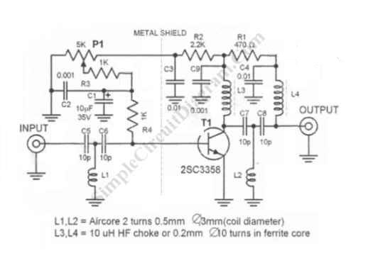
UHF Antenna Booster
This antenna signal booster is designed for TV receivers operating in the UHF band (400-850 MHz) and provides an amplification of approximately 10 to 15 dB. The schematic diagram of the circuit indicates that special attention is necessary for the...
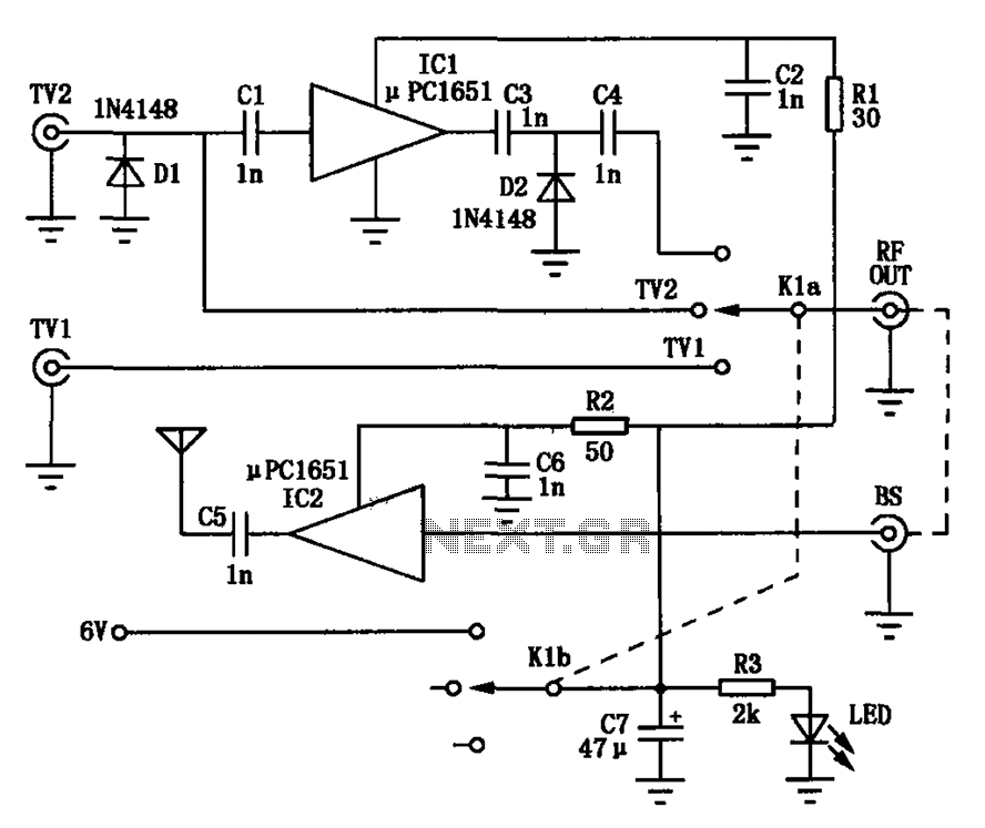
TV signal amplifying circuit diagram conversion
Amplification is utilized to convert video output signals from various devices, such as VCRs and DVD players, which often require amplification of weak output signals. Additionally, it can transmit radio frequency signals over a radius of approximately 7 meters, enhancing...
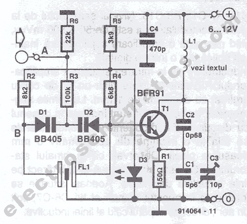
UHF Transmitter Circuit
This UHF transmitter is designed for low power applications such as remote controls for garage doors, operating systems, and wireless alarms. This UHF FM transmitter is equipped with...
This UHF transmitter operates within the Ultra High Frequency (UHF) band, which typically...
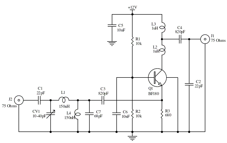
15db uhf tv antenna booster
This is a UHF band TV antenna preamplifier circuit with a gain of 15 dB. It is designed using the BF180 UHF transistor. The input stage consists of a band-pass filter implemented with components C1, CV1, L1, L4, C7, and...
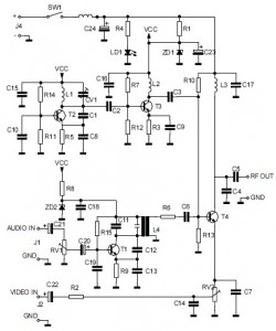
Audio/Video to UHF TV Signal Converter (Modulator)
This is the circuit diagram of an audio/video modulator. The circuit converts audio and video signals into a UHF TV signal, allowing a video signal from a camera or other source to be connected to a standard TV set. The...
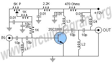
uhf antenna amplifier booster
This UHF antenna amplifier circuit, also referred to as a UHF antenna booster circuit, is designed to amplify signals within the UHF band, specifically from 400 MHz to 850 MHz. The circuit employs a single transistor and provides an amplification...
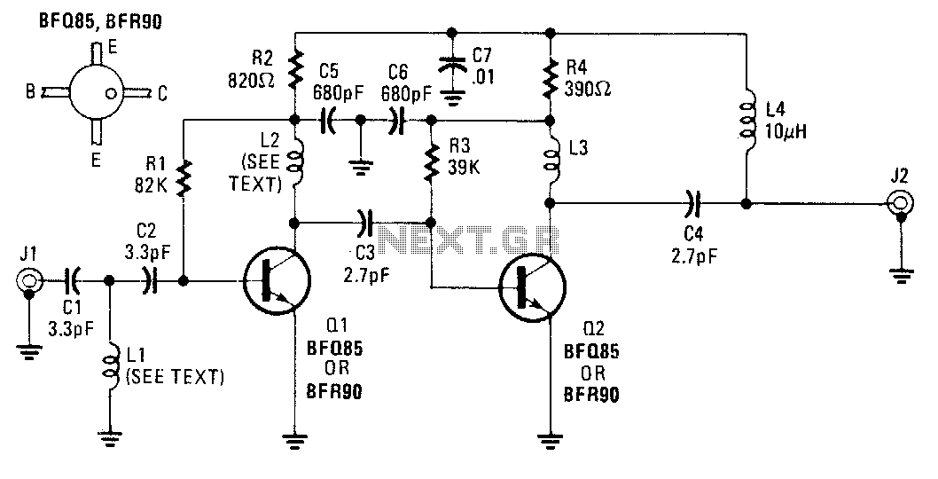
Uhf-tv-preamplifier
An inexpensive antenna-mounted UHF-TV preamplifier can add more than 25 dB of gain. The first stage of the preamplifier is biased for optimum noise performance, while the second stage is optimized for maximum gain. Additional details include Ll and L2,...
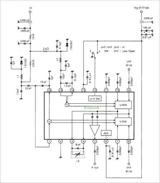
TA1284FN UHF / VHF TUNER IC (Low Phase Noise Oscillator)
TA1317ANG is a deflection processor integrated circuit (IC) designed for large and wide picture tubes. It includes an electronic width (EW) correction circuit, a vertical distortion correction circuit, and a dynamic focus correction circuit. The device can control various functions...
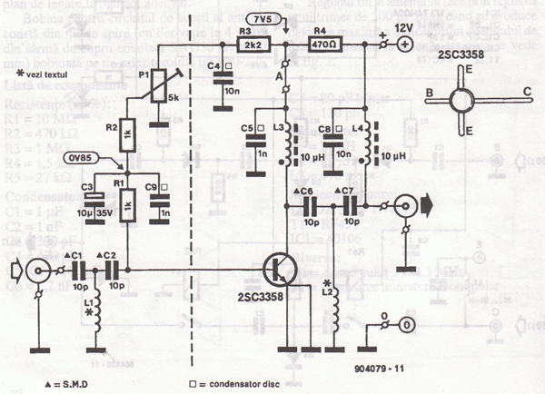
Wideband UHF Amplifier - Antenna TV Amplifier Circuit
This UHF wideband amplifier (Ultra High Frequency amplifier) provides a total gain of 10 to 15 dB in the frequency range of 400 to 850 MHz, making it suitable for areas with weak TV signals. For optimal performance, the component...