


Wideband UHF Amplifier - Antenna TV Amplifier Circuit
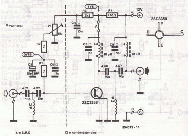
Description: This UHF wideband amplifier (Ultra High Frequency amplifier) provides a total gain of 10 to 15 dB in the frequency range of 400 to 850 MHz, making it suitable for areas with weak TV signals. For optimal performance, the component pins must be cut as short as possible. The capacitors C1, C2, C6, and C7 are surface-mounted devices (SMD). The UHF antenna TV amplifier should be housed within a metal enclosure and positioned close to the TV antenna. A simple 12V stabilized power supply is required. The amplifier can be connected directly to the power supply through a coaxial cable from the TV antenna, but a 10 to 100 µH coil must be included in the power line. The TV set will connect to the UHF amplifier via a small coupling capacitor.
The UHF wideband amplifier is designed to enhance weak television signals in the specified frequency range. Its architecture typically includes a series of low-noise amplifying stages to achieve the specified gain while maintaining signal integrity. The choice of SMD capacitors (C1, C2, C6, and C7) is crucial, as these components help filter out unwanted frequencies and stabilize the amplifier's performance.
The metal enclosure serves multiple purposes: it protects sensitive electronic components from external interference and environmental factors, and it helps to minimize electromagnetic interference (EMI) that could degrade the amplifier's performance. Proper grounding of the enclosure is essential to ensure effective shielding.
The power supply, rated at 12V, should be stabilized to prevent voltage fluctuations that could affect the amplifier's performance. The inclusion of a 10 to 100 µH coil on the power line is a critical design feature; it acts as an inductor that filters out high-frequency noise from the power supply, ensuring that only the desired signals are amplified.
Connecting the amplifier to the TV set through a coupling capacitor is a common practice in RF design. This capacitor allows AC signals to pass while blocking DC components, preventing potential damage to the TV’s circuitry. The amplifier should be carefully calibrated to optimize the gain and ensure that the output signal is within the acceptable range for the connected TV.
In summary, the design and implementation of a UHF wideband amplifier involve careful consideration of component selection, housing, power supply design, and signal coupling techniques to achieve reliable performance in enhancing weak TV signals.This UHF wideband amplifier(Ultra High Frequency amplifier) has a total gain of 10 to 15 dB in the 400 850 MHz domain frequency so it can be used where the tv signal is weak. For this UHF antenna tv amplifier to work correctly you need to cut the components pins as short as possible.
C1, C2, C6, C7 are SMD type ( surface mounted ). This antenn a tv amplifier or uhf wideband amplifier need to be build inside of a metal box and then connected close to the tv antenna. The power supply is a simple 12V stabilized source. The antenna tv amplifier can be connected directly to the power supply thru coaxial cable of the tv antenna but you need a 10 100uH coil on the alimentation line.
The tv set will be connected to the uhf amplifier thru a small coupling capacitor.
The UHF wideband amplifier is designed to enhance weak television signals in the specified frequency range. Its architecture typically includes a series of low-noise amplifying stages to achieve the specified gain while maintaining signal integrity. The choice of SMD capacitors (C1, C2, C6, and C7) is crucial, as these components help filter out unwanted frequencies and stabilize the amplifier's performance.
The metal enclosure serves multiple purposes: it protects sensitive electronic components from external interference and environmental factors, and it helps to minimize electromagnetic interference (EMI) that could degrade the amplifier's performance. Proper grounding of the enclosure is essential to ensure effective shielding.
The power supply, rated at 12V, should be stabilized to prevent voltage fluctuations that could affect the amplifier's performance. The inclusion of a 10 to 100 µH coil on the power line is a critical design feature; it acts as an inductor that filters out high-frequency noise from the power supply, ensuring that only the desired signals are amplified.
Connecting the amplifier to the TV set through a coupling capacitor is a common practice in RF design. This capacitor allows AC signals to pass while blocking DC components, preventing potential damage to the TV’s circuitry. The amplifier should be carefully calibrated to optimize the gain and ensure that the output signal is within the acceptable range for the connected TV.
In summary, the design and implementation of a UHF wideband amplifier involve careful consideration of component selection, housing, power supply design, and signal coupling techniques to achieve reliable performance in enhancing weak TV signals.This UHF wideband amplifier(Ultra High Frequency amplifier) has a total gain of 10 to 15 dB in the 400 850 MHz domain frequency so it can be used where the tv signal is weak. For this UHF antenna tv amplifier to work correctly you need to cut the components pins as short as possible.
C1, C2, C6, C7 are SMD type ( surface mounted ). This antenn a tv amplifier or uhf wideband amplifier need to be build inside of a metal box and then connected close to the tv antenna. The power supply is a simple 12V stabilized source. The antenna tv amplifier can be connected directly to the power supply thru coaxial cable of the tv antenna but you need a 10 100uH coil on the alimentation line.
The tv set will be connected to the uhf amplifier thru a small coupling capacitor.
Wide band high frequency amplifier circuit
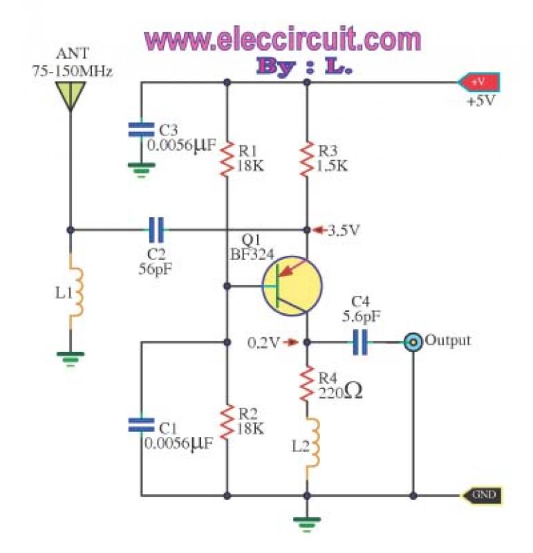
This is a wideband high-frequency amplifier circuit designed for a frequency range between 75-150 MHz. It utilizes a PNP transistor amplifier to enhance signal strength before it reaches the receiver of devices such as phones, FM radios, or amateur radios....
uhf tv transmitter circuit
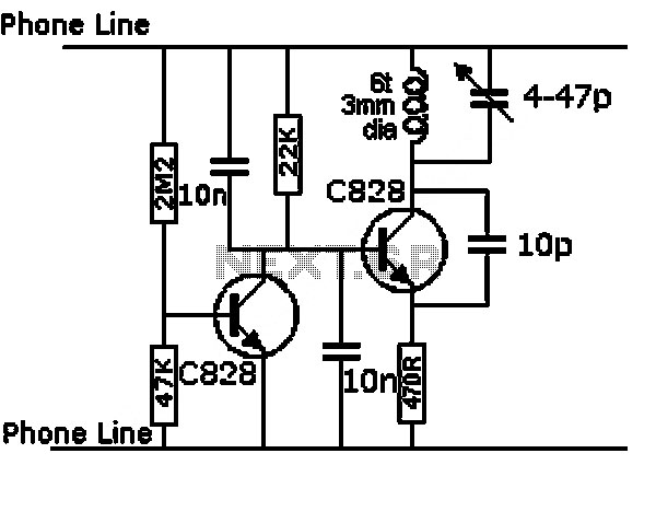
This is a design circuit for a UHF transmitter. The TV transmitter operates within the UHF frequency range of 470-580 MHz, specifically on channels 21-34. It can transmit signals over distances of 30-100 meters using a cable length of 10-20...
BF494 Transistor For UHF Indicator Wavemeter
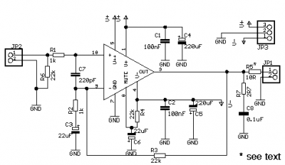
The following circuit illustrates a UHF Indicator Wavemeter Circuit Diagram. This circuit utilizes dual BF494 transistors. Features: the oscillator is...
The UHF Indicator Wavemeter Circuit is designed to measure and indicate the frequency of ultra-high frequency (UHF) signals. The circuit primarily...
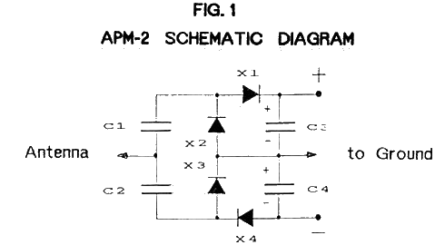
Ambient Power Module
The Ambient Power Module (APM) is a straightforward electronic circuit that, when connected to an antenna and an earth ground, can deliver a low voltage output of up to several milliwatts. An optimal setup involves a long wire antenna approximately...
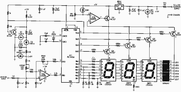
Wide Band Fuel Mixture Display
This document is an introduction to the Wideband Fuel Mixture Display (FMD). We modified the original Silicon Chip Fuel Mixture Display (that used a narrowband sensor) for use as a display for the DIY-WB wideband oxygen sensor controller. After first...
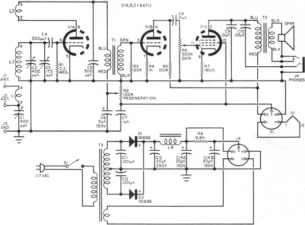
One Receiver
RF Cafe visitor David M. requested the scanning and posting of an article from the January 1963 edition of Popular Electronics, authored by Philip Hatfield from the Receiving Tube Department of General Electric. The article describes a straightforward design utilizing...
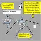
Ground pole & 2-Half-Wave Dipole Antenna
This Antenna is most widely used all over the world. For example, when you see a police car it has a transmitter with Ground Pole Antenna. The body of the car serves as ground. It accepts load from a 50-ohm...
RECEIVER BUILDING BLOCKS
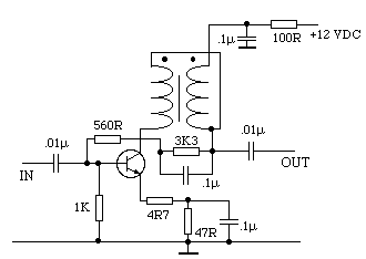
This amplifier has about 20dB of gain, bandwidth of 100MHz and noise figure of about 7dB. The output transformer is 8 turns bifilar wound on a ferrite core. Use a medium power UHF transistor 2N5109, 2N3866, 2N4427 or similar. The...
rf modem robotics project using pic16f84 microcontroller
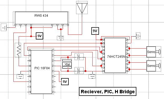
RF technology is an exciting field to incorporate into electronic designs. However, for beginners, constructing reliable RF transmitters and receivers can be challenging.
RF (Radio Frequency) technology plays a crucial role in modern communication systems, enabling wireless data transmission over various...