


UHF TV Antenna Booster Circuit With BF180 Transistor
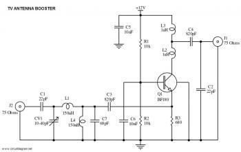
Description: This is a straightforward circuit for a UHF band TV antenna booster that provides a gain of 15 dB. This low-cost antenna booster is simple and easy to construct.
The UHF band TV antenna booster circuit is designed to enhance the signal strength received by UHF antennas, which are commonly used for digital television broadcasting. The circuit typically consists of a low-noise amplifier (LNA) that amplifies weak signals captured by the antenna. The gain of 15 dB indicates that the amplifier will increase the signal strength significantly, improving the quality of the received television signals and reducing the likelihood of pixelation or loss of picture.
The primary components of this circuit include the LNA, which is usually an integrated circuit (IC) designed for RF applications, along with passive components such as resistors, capacitors, and possibly an inductor for filtering purposes. The power supply for the circuit can be derived from a standard DC source, and it is essential to ensure that the voltage and current ratings are compatible with the LNA specifications.
The circuit layout should be designed to minimize interference and maintain signal integrity. This can be achieved by keeping the input and output traces short and using proper grounding techniques. Additionally, the use of a suitable enclosure can help shield the circuit from external electromagnetic interference.
To construct the antenna booster, the components should be assembled on a printed circuit board (PCB) or a perfboard, ensuring that all connections are secure and that the layout adheres to RF design principles. Once assembled, the circuit can be tested by connecting it to a UHF antenna and measuring the output signal strength using a signal strength meter or a compatible television receiver.
Overall, this UHF band TV antenna booster circuit offers a cost-effective solution for improving TV reception in areas with weak signal coverage, making it a valuable addition to any home entertainment system.This is a very simple circuit of UHF band TV antenna booster with 15dB gain power. This low cost antenna booster is simple and easy to build. This ..
The UHF band TV antenna booster circuit is designed to enhance the signal strength received by UHF antennas, which are commonly used for digital television broadcasting. The circuit typically consists of a low-noise amplifier (LNA) that amplifies weak signals captured by the antenna. The gain of 15 dB indicates that the amplifier will increase the signal strength significantly, improving the quality of the received television signals and reducing the likelihood of pixelation or loss of picture.
The primary components of this circuit include the LNA, which is usually an integrated circuit (IC) designed for RF applications, along with passive components such as resistors, capacitors, and possibly an inductor for filtering purposes. The power supply for the circuit can be derived from a standard DC source, and it is essential to ensure that the voltage and current ratings are compatible with the LNA specifications.
The circuit layout should be designed to minimize interference and maintain signal integrity. This can be achieved by keeping the input and output traces short and using proper grounding techniques. Additionally, the use of a suitable enclosure can help shield the circuit from external electromagnetic interference.
To construct the antenna booster, the components should be assembled on a printed circuit board (PCB) or a perfboard, ensuring that all connections are secure and that the layout adheres to RF design principles. Once assembled, the circuit can be tested by connecting it to a UHF antenna and measuring the output signal strength using a signal strength meter or a compatible television receiver.
Overall, this UHF band TV antenna booster circuit offers a cost-effective solution for improving TV reception in areas with weak signal coverage, making it a valuable addition to any home entertainment system.This is a very simple circuit of UHF band TV antenna booster with 15dB gain power. This low cost antenna booster is simple and easy to build. This ..
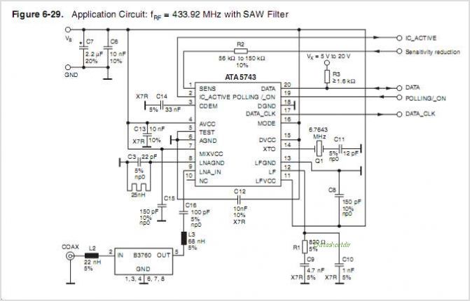
ATA5743 ATA5743 UHF ASK/FSK Receiver
The ATA5760 and ATA5761 are multi-chip PLL receiver devices provided in an SO20 package. They have been specifically designed to meet the requirements of RF low-cost data transmission systems with data rates ranging from 1 kBaud to 10 kBaud, utilizing...
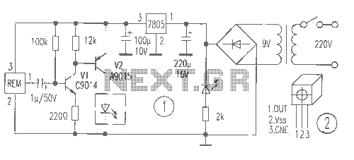
Simply by remote control law circuit diagram
The receiver provides two TV signals, one for the living room and another for the bedroom, along with a satellite receiver. Watching television in the bedroom is convenient in Taiwan; however, when watching television in the living room, it can...
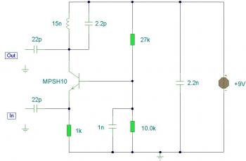
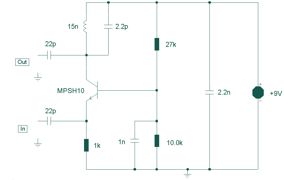
uhf tv pre amplifier
This is another UHF-TV preamplifier circuit diagram that is simpler than the previous UHF TV preamplifier. This circuit is based on the MPSH10 transistor. Alternatives that can be used to replace the MPSH10 include the BF180 and BCY90. The tuned...
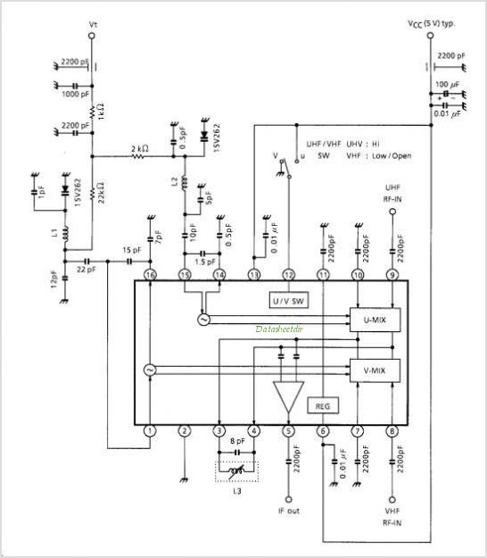
TA1284FN UHF / VHF TUNER IC (Low Phase Noise Oscillator)
TA1317ANG is a deflection processor integrated circuit (IC) designed for large and wide picture tubes. It includes an electronic width (EW) correction circuit, a vertical distortion correction circuit, and a dynamic focus correction circuit. The device can control various functions...
UHF Preamplifier
This circuit is designed to work at UHF frequencies in the range 450-800MHz. It has a gain of around 10dB and is suitable for boosting weak TV signals. The circuit is shown below.
The described circuit operates within the Ultra High...
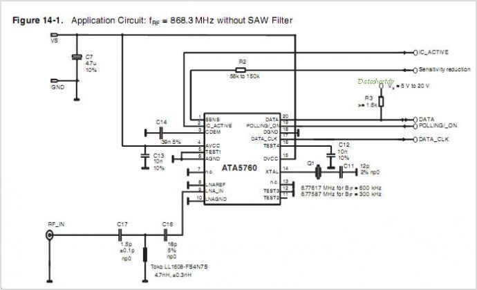
ATA5760 ATA5760 UHF ASK/FSK Receiver
The ATA6823 is designed specifically for automotive applications that require high-power motors. It provides four high-current gate driver outputs capable of driving a wide range of n-channel power MOSFETs in a full-bridge configuration. A fully integrated charge pump with external...
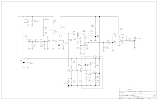
UHF Audio Video Sender Circuit
This audio-video circuit enables wireless audio and visual transmission to a television. The television functions as a receiver, eliminating the necessity for a separate monitor. It can also be connected to a VCR or CCD camera, and can be configured...
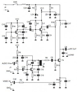
Audio/Video to UHF TV Signal Converter (Modulator) circuit diagram
This is the circuit diagram of an audio/video modulator. The circuit converts audio and video signals into a UHF TV signal. It is designed to connect a video signal originating from a camera or other video source to a standard...
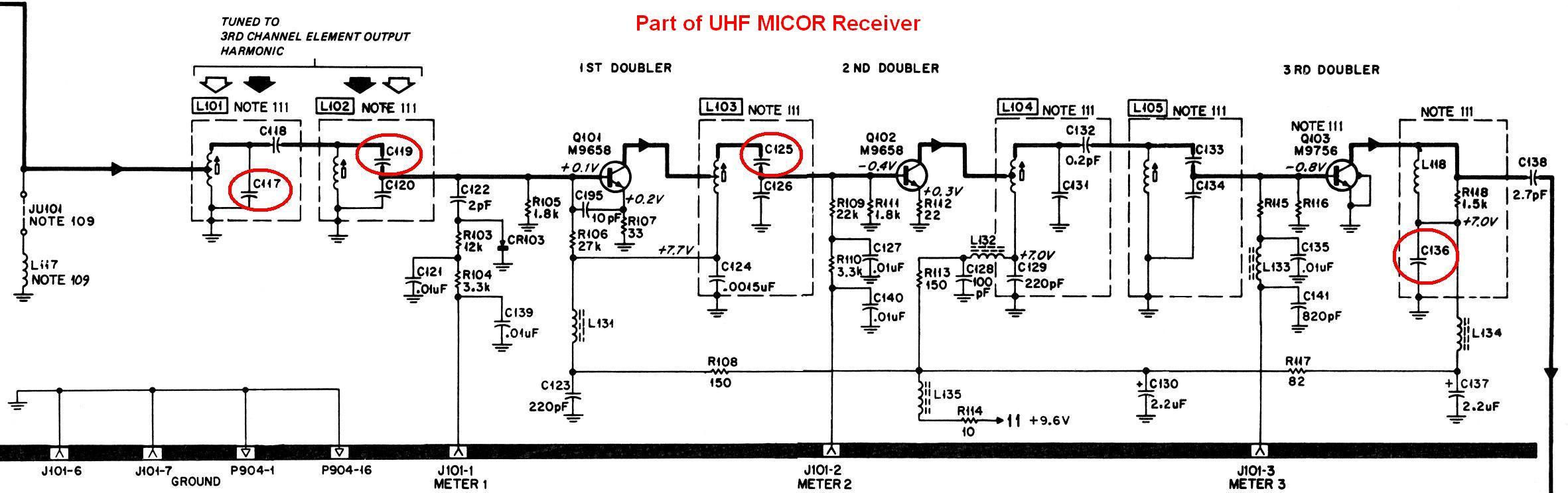
Improving the MICOR Receiver for 435-450 MHz
This document provides a detailed explanation of a procedure to modify a UHF MICOR "M" range (450-470 MHz) receiver board for optimal operation within the 435-450 MHz range. This enhancement builds upon Kevin's text-only article. These receivers are typically found...