
rf probe circuit
RF Probe Circuits are essential tools for testing and analyzing radio frequency signals in various applications, including telecommunications, broadcasting, and electronic testing. These circuits allow engineers and technicians to measure the strength and quality of RF signals, making them invaluable for troubleshooting and development purposes.
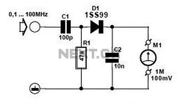
Typically, an RF probe circuit consists of a few key components: an antenna or coupling device for signal reception, an amplifier to boost the signal strength, and a detection circuit to convert the RF signal into a readable format. The design may also include filters to eliminate unwanted frequencies and improve measurement accuracy.
The antenna can be a simple wire or a more sophisticated design depending on the frequency range of interest. The amplifier is usually a low-noise amplifier (LNA) to ensure that the signal integrity is maintained during processing. The detection circuit may employ a diode or a specialized RF detector IC to convert the RF signal into a DC voltage that can be easily measured on a multimeter or oscilloscope.
When designing an RF probe circuit, considerations such as impedance matching, bandwidth, and noise performance are critical for achieving accurate measurements. Proper layout and grounding techniques are also essential to minimize interference and ensure reliable operation.
Users can find numerous resources online, including schematics, component lists, and assembly instructions, to build their own RF Probe Circuits. These resources often include detailed explanations of each component's role and the overall function of the circuit, providing a comprehensive understanding of RF measurement techniques.Good information about RF Probe Circuit. You can learn and download RF Probe Circuit online.. 🔗 External reference
Related Circuits
The 1C foot VIII developed a training device, utilizing the trigger terminal CI for a positive input pulse. It concludes by providing a quotient output level. The system involves a commercial electric circuit featuring a buck converter, which limits...
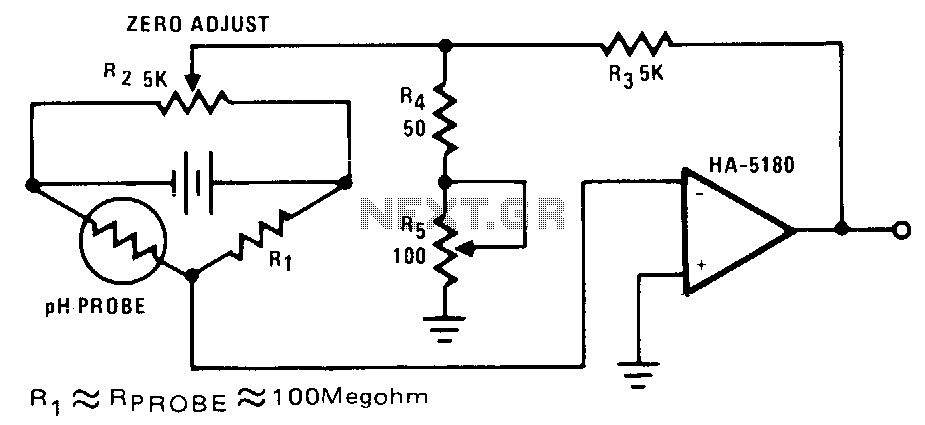
The highest sensitivity is attained when R1 is roughly equal to the probe resistance. The circuit can be calibrated to zero using R2, while R5 regulates the full-scale voltage. The relationship between pH and output voltage may not be...
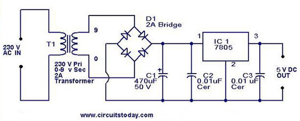
A 5V power supply using IC 7805 is designed and explained with a neat circuit diagram. The circuit for a 5V power supply utilizing the IC 7805 voltage regulator is a straightforward and efficient design that provides a stable output...
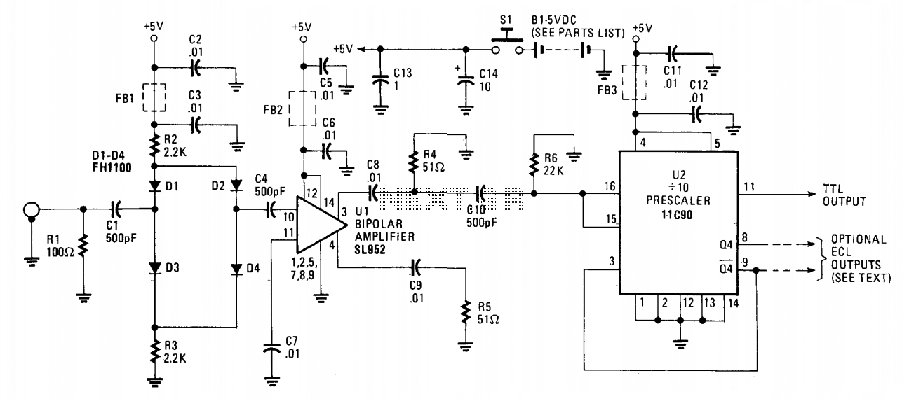
The 650 MHz prescaler probe's input is terminated by resistor R1 and is fed through C1 to the diode limiter composed of diodes D1 through D4. These diodes are forward-biased by the +5 volt supply for small input signals...
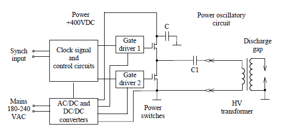
Simulate the electric field within a gas-filled discharge gap generated by a radio frequency voltage generator. The circuit, provided by the experimenters at a distance, is depicted in the accompanying image. The numerical values are as follows: C1 =...
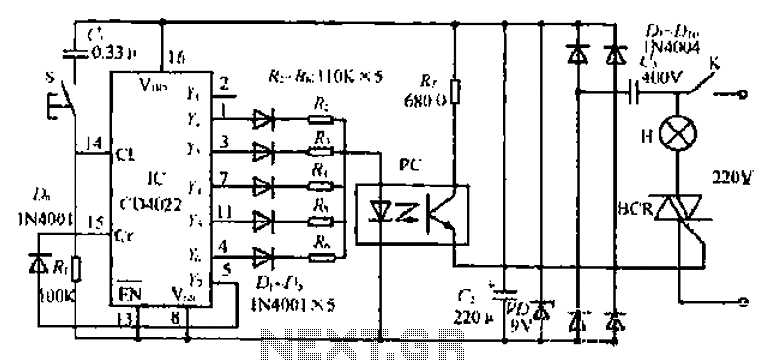
This simple circuit is the electronic version of the combination lock. Using the special purpose LS7220 digital lock IC, the circuit allows a 4 digit combination of your choice to activate a relay for a set period of time....