
650Mhz amplifying prescaler probe
The 650 MHz prescaler probe is designed to effectively manage input signals within its operational range, ensuring accurate signal processing through a series of well-defined components. The input termination via resistor R1 ensures a proper impedance match, which is critical for minimizing reflections and maximizing signal integrity. Capacitor C1 serves as a coupling element, allowing the AC component of the incoming signal to pass while blocking any DC offset, which is essential for the proper operation of the diode limiter.
The diode limiter, composed of diodes D1 through D4, functions as a protective stage. It is configured to clamp the input signal, preventing excessive voltage levels from damaging subsequent components. The forward bias provided by the +5 volt supply ensures that small signals are passed effectively to the amplifier U1. When larger signals are encountered, the diodes begin to turn off, which reduces the signal amplitude and protects the amplifier from saturation.
Integrated circuit U1, the Plessey SL952, operates at high frequencies up to 1 GHz, delivering substantial gain in the range of 20 to 30 dB. This gain is critical for amplifying the weak signals received from the diode limiter. The configuration of pins 10 and 11 allows for differential input, enhancing noise immunity and improving overall performance.
The prescaler U2, the 11C90, is specifically designed for high-speed applications, capable of dividing the input frequency by a factor of ten. The internal reference voltage at pin 15 stabilizes the operation of the prescaler, ensuring that the output frequency remains consistent. The ECL-to-TTL conversion capability integrated within U1 simplifies the design by negating the need for additional conversion circuitry, streamlining the overall layout and reducing component count.
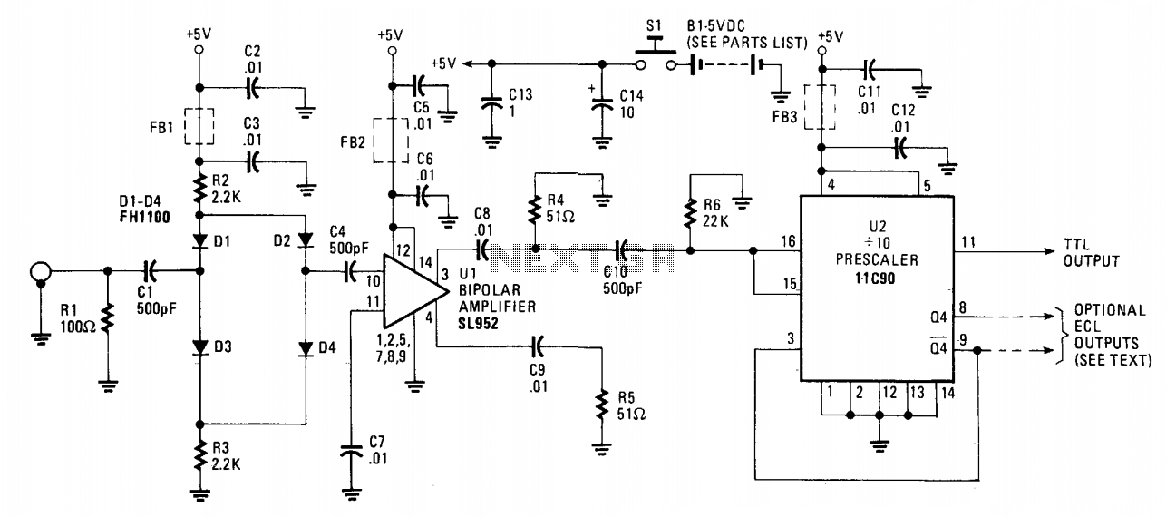
The output signals from U2 can be utilized in various applications, particularly in digital counters and frequency measurement systems. The availability of ECL outputs at pins 8 and 9 provides flexibility for interfacing with other ECL-compatible devices. The design considerations, including the option to leave pin 13 open to conserve power, demonstrate an emphasis on efficiency without compromising performance. Overall, this circuit design exemplifies a careful balance between functionality, protection, and integration, making it suitable for high-frequency signal processing applications.The 650 MHz Prescaler Probe's input is terminated by resistor Rl and is fed through Cl to the diode limiter composed ofD1 through D4. Those diodes are forward-biased by the +5 volt supply for small-input signals and, in turn, feed the signal to Ul.
However, for larger input signals, diodesD1 through D4 will start to turn off, passing less of the signal, and, thus, attenuating it. But even in a full-off state, the FHllOO-type diodes will always pass a small part of the input to Ul because of capacitive leakage within the diodes.
Integrated circuit Ul, a Plessey SL952 bipolar amplifier, capable of 1 GHz operation, provides 20 to 30 dB of gain. The input signal is supplied to pin 10, Ul with the other input (pin 11) is bypassed to ground. The output signal is taken at pin 3 and pin 4, with pin 3 loaded by R4 and pin 4 by R5. Integrated circuit 11C90, U2, is a high-speed prescaler capable of 650 MHz operation configured for a divide-by-10 format. A reference voltage internally generated appears at pin 15 and is tied to pin 16, the clock input. This centers the capacitive-coupled input voltage from Ul around the switching threshold-voltage level.
An ECL-to-TTL converter in Ul provides level conversion to drive TTL input counters by typing pin 13 low. Therefore, no external ECL to TTL converter is required at the pin 11 output. On the other hand, ECL outputs are available at U2, pin 8 (Q4) and at pin 9 (Q4), if desired. In that circuit configuration, pin 13 is left open, and U2 will use less power. 🔗 External reference
Related Circuits
The above picture illustrates an audio logic level probe circuit, which consists of a voltage comparator, a multivibrator, and piezoelectric ceramics (HTD). The multivibrator and piezoelectric components together form the audio circuit, which operates at an audio frequency to...
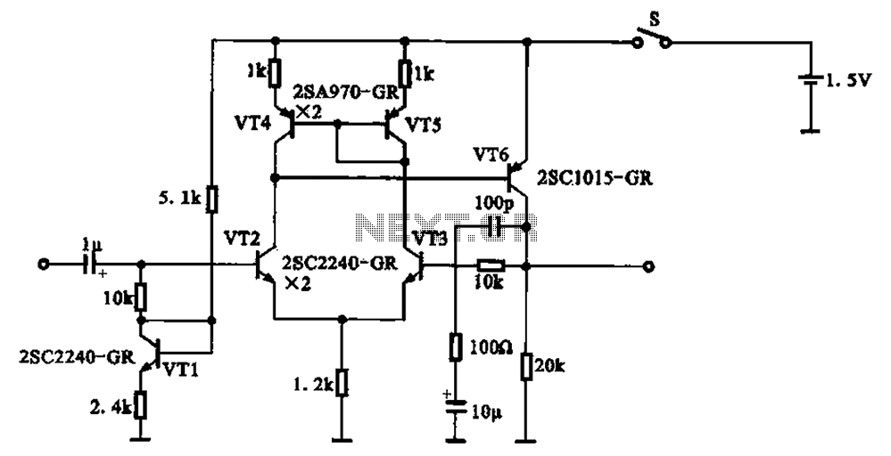
A 1.5V-powered microphone signal amplifying circuit is designed with a power supply for the microphone signal amplification. The circuit primarily consists of a differential amplifier formed by transistors VT2 and VT3. Additionally, VT6 functions as a common emitter voltage...
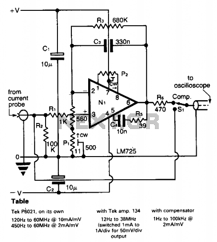
A clamp-on current probe, such as the Tektronix P6021, is an effective tool for displaying current waveforms on an oscilloscope. However, its low-frequency response is somewhat limited, as indicated in the accompanying table. The more sensitive range of the...
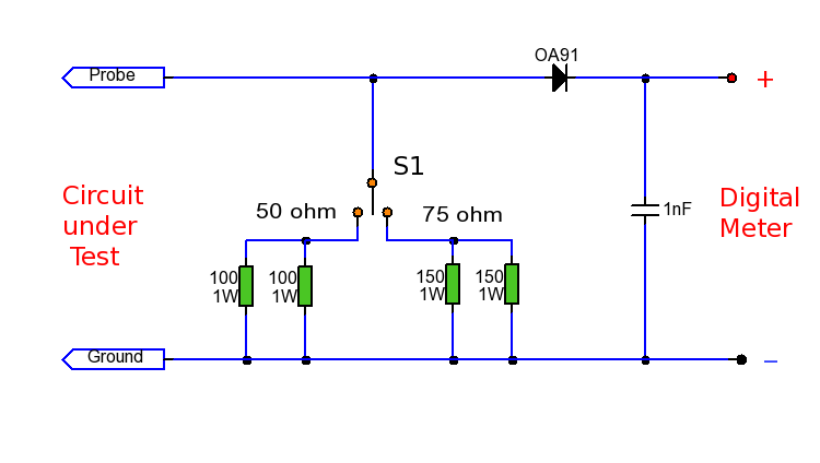
This RF probe is designed for use at High Frequency (HF) or Ultra High Frequency (UHF) with both 50 and 75 ohm coaxial cables. It can measure RF voltage under both load and no-load conditions, enabling it to function...
This project is based on a probe logic states, capable of measuring levels from TTL (5v) to state levels of PLC's (24v). For this we have employed the use of the PIC 12F683 microcontroller, which by its nature is...
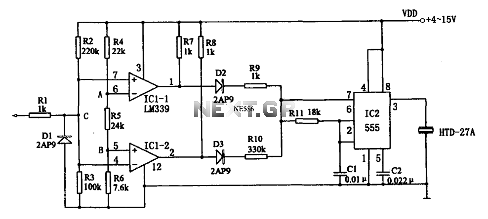
The acoustic logic level probe circuit consists of a voltage comparator, multivibrator, piezoelectric ceramics (HTD), and other components. The configuration of the audio circuit determines the frequency of the sound level to assess the logic levels of TTL or...