


irbot
#infra-red
#object detection
#BASIC Stamp
#IR LEDs
#obstacle avoidance
#CDS photocells
#light intensity
#modes of operation
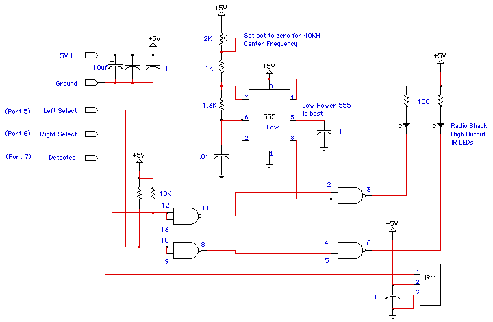
Description: An infrared object detection system has been constructed using high-output infrared (IR) LEDs. The controller for the robot is based on the Parallax BASIC Stamp I. The software version, as of October 9, 1998, provides three operational modes for the IRBOT. The default mode focuses on object avoidance, but additional modes have been implemented utilizing CDS photocells that adjust resistance according to light intensity. These photocells are positioned at the front of the IRBOT and angled approximately 30 degrees outward. The updated code enables the robot to either avoid light (photophobic) or seek light (phototropic). The mode is selected by activating one of the IR sensors for two seconds upon powering on the device.
For those interested in building this system, it is recommended to acquire the Scott Edwards book and a Parallax Stamp 1.4 rev. D. The rev D version comes with a carrier board, eliminating the need for additional components to facilitate signal transmission. The Scott Edwards book includes programming software for the Stamp and instructions for creating the necessary programming cable to connect the Stamp to a DOS machine. The book is priced around $30, and the Stamp rev D is approximately $35. This setup provides a BASIC language-interpreting microcontroller, alongside a few integrated circuits, resistors, capacitors, and interconnection methods, all of which can be sourced from local electronics retailers.
The circuit operates by modulating an IR LED at 40 kHz, which corresponds to the center frequency of the Sharp GPIU5 IR Decoder module. It is important to verify the frequency of the GPIU modules available, as some may operate at 38 kHz, which is sufficiently close for functionality. When the modulated IR beam reflects off an object, the IR module responds by outputting a logic low signal. The circuit's logic flow begins with the microcontroller enabling the left IR LED by sending a logic low signal to that pin, followed by checking for a response. The microcontroller can then switch to a logic high on the left IR LED and a logic low on the right IR LED, allowing it to ascertain the presence of an object to the left, right, or directly ahead, and respond accordingly.
The design may be considered overengineered, as a simpler 555 timer-based version did not perform satisfactorily and was replaced with a PIC-based solution. A 2 kΩ potentiometer in the 555 timer circuit allows for sensitivity adjustment by shifting away from the 40 kHz frequency. Alternatively, clear cellophane tape can be used over the face of the IR detector module to modify sensitivity, though this method has not been tested. The software identifies response points from the circuit and controls the left or right LED for object detection. Capacitors of 1 µF, located near the 555 timer, should be as close as possible to the 74LS00 chip and the IR module to ensure optimal performance. If a 1.3 kΩ resistor for the 555 timer is unavailable, a combination of a 3.3 kΩ and a 2.2 kΩ resistor in parallel can be used as a substitute. Regular checks on the circuit's center frequency may be necessary, as capacitor values can vary by ±20%. The construction of the circuit was accomplished using prototyping boards and point-to-point soldering, which may be cumbersome; alternative methods may be more efficient.I decided to build an infra-red object detection system using High Output IR LEDs. For the controller of the robot I used the Parallax BASIC Stamp I. The latest greatest version of the software, at least as of 10/9/98, gives IRBOT three modes of operation. The default mode just does object avoidance, fun in itself, but I wanted more. So I added two new modes that are based on the CDS photocells that change resistance based on light intensity.
These are mounted in the front of the IRBOT and angled outward at about 30 degrees or so. The current code now has the ability to be light avoiding (photophobic) or light seeking (phototrophic). The mode is selected by triggering one or the other IR sensor for two seconds when you first turn it on.
The specifics are further down this page. If you want to build this too, my advice is get the Scott Edwards book above and a Parallax Stamp 1. 4 rev. D. The rev D comes on a carrier board so no other expense is needed to get signals to and from it. The Scott Edwards book comes with programming software for the Stamp and it also comes with construction details to make the programming cable you will need to connect the Stamp to your DOS machine. The book is about $30 and the Stamp rev D is about $35. You now have a BASIC language interpreting microcontroller. You now only need two simple integrated circuits, some resistors, some capacitors, and a way to tie them all together.
All of these components may be obtained at your local Radio Shack. This circuit works by modulating an IR LED at 40KHz, which is the center frequency of the Sharp GPIU5 IR Decoder module. Check what you get at Radio Shack, some GPIU modules are 38KHz, which really, is close enough anyway.
When the modulated IR beam bounces off of something the IR module will react to the signal by giving a logic low on its output. The logic of this circuit functions by first allowing the microcontroller to enable the left IR LED by putting a logic low on that pin, then checking for a response.
The microcontroller can then put a logic high on the left IR LED and put a logic low on the right IR LED, and looking for a response. From this sequence the microcontroller can determine if there is an object to the left, right or straight ahead, and react accordingly.
With my usual "belt and suspenders" design attitude (as was pointed out to me) I probably overdesigned my circuit. Maybe so, but the trimmed down 555 only version of this circuit didn`t work very well, its been scrapped in favor of a PIC based solution ( see below.
) The 2K pot in the 555 circuit is there to allow you to adjust the sensitivity of the detection circuit by moving further away from 40KHz. You may leave this out and elect to put clear cellophane tape over the face of the IR detector module instead - I haven`t tried that yet.
I have noted where my software looks for the response from the circuit and where it enables the left or right LED for searching. The. 1uf cap on next to the 10uf cap in the upper left of the schematic is located physically close to the 555 timer.
IRM is the IR detection module. If you can`t get a 1. 3K resistor for the 555 timer, a 3. 3K and 2. 2K resistor in parallel will come close enough to that value. You sometimes need to check the circuit for proper center frequency, or fiddle with it as the. 1uf caps are usually +or- 20% of their posted value. Make those. 1uf caps close to the 74LS00 chip and the 555 and IR module as you can. I built my circuits by using prototyping board and point-to-point soldering of wires. This is a pain, if you know of a better way, do it. As a reference, below is a first-pass a
For those interested in building this system, it is recommended to acquire the Scott Edwards book and a Parallax Stamp 1.4 rev. D. The rev D version comes with a carrier board, eliminating the need for additional components to facilitate signal transmission. The Scott Edwards book includes programming software for the Stamp and instructions for creating the necessary programming cable to connect the Stamp to a DOS machine. The book is priced around $30, and the Stamp rev D is approximately $35. This setup provides a BASIC language-interpreting microcontroller, alongside a few integrated circuits, resistors, capacitors, and interconnection methods, all of which can be sourced from local electronics retailers.
The circuit operates by modulating an IR LED at 40 kHz, which corresponds to the center frequency of the Sharp GPIU5 IR Decoder module. It is important to verify the frequency of the GPIU modules available, as some may operate at 38 kHz, which is sufficiently close for functionality. When the modulated IR beam reflects off an object, the IR module responds by outputting a logic low signal. The circuit's logic flow begins with the microcontroller enabling the left IR LED by sending a logic low signal to that pin, followed by checking for a response. The microcontroller can then switch to a logic high on the left IR LED and a logic low on the right IR LED, allowing it to ascertain the presence of an object to the left, right, or directly ahead, and respond accordingly.
The design may be considered overengineered, as a simpler 555 timer-based version did not perform satisfactorily and was replaced with a PIC-based solution. A 2 kΩ potentiometer in the 555 timer circuit allows for sensitivity adjustment by shifting away from the 40 kHz frequency. Alternatively, clear cellophane tape can be used over the face of the IR detector module to modify sensitivity, though this method has not been tested. The software identifies response points from the circuit and controls the left or right LED for object detection. Capacitors of 1 µF, located near the 555 timer, should be as close as possible to the 74LS00 chip and the IR module to ensure optimal performance. If a 1.3 kΩ resistor for the 555 timer is unavailable, a combination of a 3.3 kΩ and a 2.2 kΩ resistor in parallel can be used as a substitute. Regular checks on the circuit's center frequency may be necessary, as capacitor values can vary by ±20%. The construction of the circuit was accomplished using prototyping boards and point-to-point soldering, which may be cumbersome; alternative methods may be more efficient.I decided to build an infra-red object detection system using High Output IR LEDs. For the controller of the robot I used the Parallax BASIC Stamp I. The latest greatest version of the software, at least as of 10/9/98, gives IRBOT three modes of operation. The default mode just does object avoidance, fun in itself, but I wanted more. So I added two new modes that are based on the CDS photocells that change resistance based on light intensity.
These are mounted in the front of the IRBOT and angled outward at about 30 degrees or so. The current code now has the ability to be light avoiding (photophobic) or light seeking (phototrophic). The mode is selected by triggering one or the other IR sensor for two seconds when you first turn it on.
The specifics are further down this page. If you want to build this too, my advice is get the Scott Edwards book above and a Parallax Stamp 1. 4 rev. D. The rev D comes on a carrier board so no other expense is needed to get signals to and from it. The Scott Edwards book comes with programming software for the Stamp and it also comes with construction details to make the programming cable you will need to connect the Stamp to your DOS machine. The book is about $30 and the Stamp rev D is about $35. You now have a BASIC language interpreting microcontroller. You now only need two simple integrated circuits, some resistors, some capacitors, and a way to tie them all together.
All of these components may be obtained at your local Radio Shack. This circuit works by modulating an IR LED at 40KHz, which is the center frequency of the Sharp GPIU5 IR Decoder module. Check what you get at Radio Shack, some GPIU modules are 38KHz, which really, is close enough anyway.
When the modulated IR beam bounces off of something the IR module will react to the signal by giving a logic low on its output. The logic of this circuit functions by first allowing the microcontroller to enable the left IR LED by putting a logic low on that pin, then checking for a response.
The microcontroller can then put a logic high on the left IR LED and put a logic low on the right IR LED, and looking for a response. From this sequence the microcontroller can determine if there is an object to the left, right or straight ahead, and react accordingly.
With my usual "belt and suspenders" design attitude (as was pointed out to me) I probably overdesigned my circuit. Maybe so, but the trimmed down 555 only version of this circuit didn`t work very well, its been scrapped in favor of a PIC based solution ( see below.
) The 2K pot in the 555 circuit is there to allow you to adjust the sensitivity of the detection circuit by moving further away from 40KHz. You may leave this out and elect to put clear cellophane tape over the face of the IR detector module instead - I haven`t tried that yet.
I have noted where my software looks for the response from the circuit and where it enables the left or right LED for searching. The. 1uf cap on next to the 10uf cap in the upper left of the schematic is located physically close to the 555 timer.
IRM is the IR detection module. If you can`t get a 1. 3K resistor for the 555 timer, a 3. 3K and 2. 2K resistor in parallel will come close enough to that value. You sometimes need to check the circuit for proper center frequency, or fiddle with it as the. 1uf caps are usually +or- 20% of their posted value. Make those. 1uf caps close to the 74LS00 chip and the 555 and IR module as you can. I built my circuits by using prototyping board and point-to-point soldering of wires. This is a pain, if you know of a better way, do it. As a reference, below is a first-pass a
Infra-red Level Detector
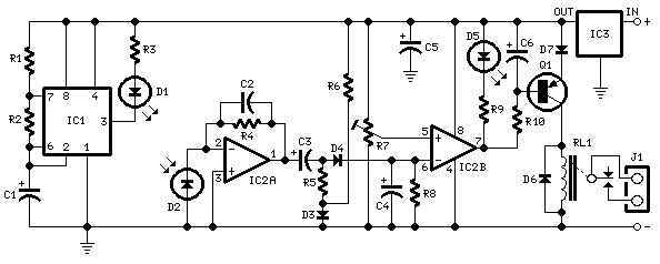
This circuit is useful in liquids level or proximity detection. It operates detecting the distance from the target by reflection of an infra-red beam. It can safely detect the level of a liquid in a tank without any contact with...
Infra-red Level Detectors
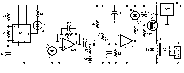
This circuit is designed for liquid level or proximity detection. It operates by measuring the distance to a target through the reflection of an infrared beam. The device can detect the level of liquid in a tank without any direct...

Infra-red Level Detector with 555
Useful for liquids level detection and proximity devices. Up to 50 cm range, optional relay operation. This circuit is useful in liquids level or proximity detection. It operates detecting the distance from the target by reflection of an infra-red beam....
Obstacle Avoiding Robot without microcontroller
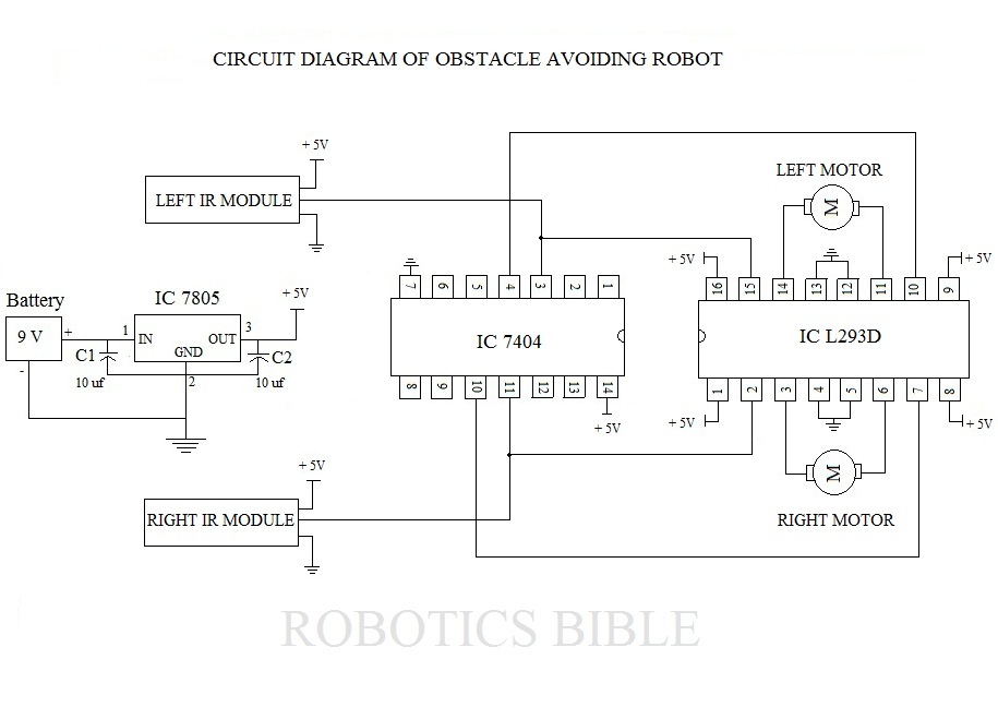
An obstacle-avoiding robot is an intelligent device that can automatically sense and navigate around obstacles in its path. It is designed without a microcontroller to simplify the circuitry and programming requirements. Understanding the circuit diagram is essential for constructing this...
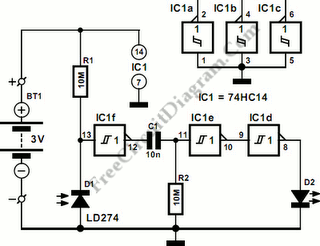
74HC11 Infra-Red Remote Control Tester
This circuit is an Infra-Red Remote Control Tester designed to verify the functionality of any remote control that transmits infrared (IR) light. It operates on a 3V battery and offers several advantages, such as its compact size and the use...
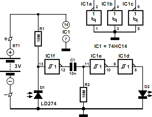
Infra-Red Remote Control Tester
This circuit is essential for quickly determining the functionality of various remote control transmitting infrared (IR) lights. It is powered by a battery and constructed from a few commonly available and inexpensive components, fitting into a compact enclosure. The Schmitt...
Obstacle Avoiding Robot without microcontroller
An obstacle-avoiding robot is an intelligent device that can automatically sense and navigate around obstacles in its path. It is designed without a microcontroller to simplify the circuitry and programming requirements. Understanding the circuit diagram is essential for constructing this...
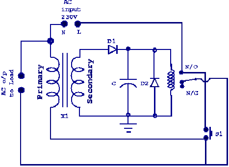
Obstacle Avoidance & Navigation for Industrial Robots
A project focused on obstacle avoidance and path tracing navigation for industrial robots. A robot is a self-guided machine capable of performing tasks autonomously. Additionally, robots often exhibit characteristics through their design or movements that give the impression of having...

Infra-Red Sensor/Monitor
The sensor/monitor depicted in the diagram activates the host system upon detecting infrared (IR) signals. It consumes very little supply current, allowing it to remain continuously operational in devices such as notebook computers or PDAs. The ultra-low current drain, with...