


Capacitive Touch Sensor
#capacitive touch
#proximity sensor
#DIY
#Halloween
#NerdKit
#lighting
#interactive
#electronics
#trick-or-treater
#sensor circuit
Description: For this special Halloween project, a spooky candy bowl was created that lights up when an unsuspecting trick-or-treater reaches in. While similar devices exist, many utilize complicated proximity sensors. The approach taken here is simpler, making it a suitable DIY project. The proximity sensor consists of a NerdKit, two pieces of aluminum foil, and some paper clips. The sensor detects the presence of a hand using principles similar to those of capacitive touch sensors found on laptop touchpads. These sensors operate on the premise that humans are primarily composed of water. When a hand approaches an electric field, it alters the capacitance enough to be detected by the sensor.
In this design, an RC circuit is set up with a capacitor and a resistor in parallel. The microcontroller unit (MCU) charges the capacitor up to 5V. Once charged, the pin is switched to input mode, disconnecting the node and allowing the capacitor to discharge through the resistor. The discharge time is related to the resistor value multiplied by the capacitance. A resistor value of 100K ohms is used to ensure the RC time constant is measurable by the MCU. The sensor comprises two sheets of aluminum foil, one connected to the MCU pin and the other to ground, forming a capacitor that the MCU charges and discharges. When a hand moves between the sheets, it alters the electric field and, consequently, the capacitance. This change results in a longer discharge time, which is detected by the microcontroller's code.
An alternative implementation could use a pin change interrupt to measure the time taken for the pin to switch to a logic low level as the voltage drops. However, a more elegant solution is employed using the Analog Comparator on the chip. The Analog Comparator compares two analog voltages and outputs a binary signal depending on which is higher. A reference voltage, set to the bandgap voltage of approximately 1.2V, is used for comparison. This reference voltage allows ample room for the pin to discharge from 5V before changing the output state. The output of the comparator can trigger an interrupt when it switches from low to high, specifically when the capacitor voltage drops below 1.2V. This enables the timing of the voltage drop using a simple timer in the interrupt handler.
This design illustrates the integration of multiple concepts and components of the MCU to achieve a functional result. The slight change in capacitance, caused by the presence of a hand, can be measured by configuring the MCU as an oscillator and timing the discharge duration. Capacitive proximity sensors operate effectively because the human body, primarily composed of water, interacts with electric fields due to water's high permittivity, which is approximately 80 times greater than that of air. When a voltage is applied between the capacitor plates, an electric field is generated, and the presence of a dielectric, such as water, reduces the electric field strength compared to air.For this special Halloween project we built a spooky candy bowl that lights up when an unsuspecting trick-or-treater reaches in. While devices like these do exist, many of them use complicated proximity sensors to spring their trap.
Here at NerdKits we enjoy doingthings a bit differently, and making it easy for you to undertake it as a DIY project. Our proximity sensor is made using nothing but a NerdKit, two pieces of aluminum foil, and some paper clips! The actual sensor used to detect the presence of a hand in explained in detail in the video, but here is an overview. Our sensor operates on the same principle that a capacitive touch sensor works on your laptop touchpad.
These capacitive touch sensors work on the premise that humans are mostly water. When you get near an electric field you alter the capacitance enough to be noticed by the sensor. In our system we set up an RC circuit with a capacitor and a resistor in parallel. We use the MCU to charge capacitor up to 5V (a digital high voltage). Then we turn the pin into an input pin, which essentially disconnects that node. This allows the capacitor to discharge through the resistor. The amount of time it takes the capacitor to discharge will be related to the resistor value times the capacitance. We pick a resistor value large enough that the RC time constant is long enough for us to measure with the MCU.
In this case 100K ohms worked great. The sensor in this case is two sheets of aluminum foil, one connected to the MCU pin, and one connected to GND. These two sheets create a capacitor that our MCU is charging and discharging. When your hands move between the two sheets, it alters the electric field, and therefore the capacitance of our tin foil contraption.
The capacitor therefore takes longer to discharge, and that is detected by the code on our microcontroller! It might be possible to implement this with a pin change interrupt, and timing how long it takes for the pin to turn into a logic low level; that is, until the voltage drops low enough to be considered a 0 on the pin.
However, we chose a slightly more elegant approach. We use the Analog Comparator on the chip. The analog comparator does exactly what its name promises: it compares two analog voltages and outputs a 0 or a 1 depending on which one is higher. The Analog Comparator also allows you to designate a reference voltage to compare against. This voltage happens to be the bandgap voltage which is about 1. 2V. This 1. 2V is low enough that it gives the pin plenty of room to discharge from 5V before it changes the output of the comparison.
You can do anything you want with the output of the comparison, but the Analog Comparator allows you to set up an interrupt to fire when the output of the comparison switches from low to high (in our case this when the voltage on our capacitor drops below 1. 2V). With that we are able to time how long it takes for the voltage to drop, using a simple timer in the interrupt handler.
This is once again a great example of multiple concepts, along with multiple parts of the MCU working together to produce a very nifty result. Something as simple as a slight change in the capacitance can be measured by turning your MCU into an oscillator, and timing how long it takes to discharge.
Capacitive proximity sensors work because people are mostly water, and water is a very polar molecule, and is easily turned to align with any applied electric field. In fact, water has a "permittivity" (dielectric constant) that is about 80 times better than air! When a given voltage is applied between the two plates of any capacitor, an electric field is created between the plates.
In the region where there`s a dielectric, the electric field is actually smaller than it is in air (for water, just 1/80th of the field strength), so your first instinct might be
In this design, an RC circuit is set up with a capacitor and a resistor in parallel. The microcontroller unit (MCU) charges the capacitor up to 5V. Once charged, the pin is switched to input mode, disconnecting the node and allowing the capacitor to discharge through the resistor. The discharge time is related to the resistor value multiplied by the capacitance. A resistor value of 100K ohms is used to ensure the RC time constant is measurable by the MCU. The sensor comprises two sheets of aluminum foil, one connected to the MCU pin and the other to ground, forming a capacitor that the MCU charges and discharges. When a hand moves between the sheets, it alters the electric field and, consequently, the capacitance. This change results in a longer discharge time, which is detected by the microcontroller's code.
An alternative implementation could use a pin change interrupt to measure the time taken for the pin to switch to a logic low level as the voltage drops. However, a more elegant solution is employed using the Analog Comparator on the chip. The Analog Comparator compares two analog voltages and outputs a binary signal depending on which is higher. A reference voltage, set to the bandgap voltage of approximately 1.2V, is used for comparison. This reference voltage allows ample room for the pin to discharge from 5V before changing the output state. The output of the comparator can trigger an interrupt when it switches from low to high, specifically when the capacitor voltage drops below 1.2V. This enables the timing of the voltage drop using a simple timer in the interrupt handler.
This design illustrates the integration of multiple concepts and components of the MCU to achieve a functional result. The slight change in capacitance, caused by the presence of a hand, can be measured by configuring the MCU as an oscillator and timing the discharge duration. Capacitive proximity sensors operate effectively because the human body, primarily composed of water, interacts with electric fields due to water's high permittivity, which is approximately 80 times greater than that of air. When a voltage is applied between the capacitor plates, an electric field is generated, and the presence of a dielectric, such as water, reduces the electric field strength compared to air.For this special Halloween project we built a spooky candy bowl that lights up when an unsuspecting trick-or-treater reaches in. While devices like these do exist, many of them use complicated proximity sensors to spring their trap.
Here at NerdKits we enjoy doingthings a bit differently, and making it easy for you to undertake it as a DIY project. Our proximity sensor is made using nothing but a NerdKit, two pieces of aluminum foil, and some paper clips! The actual sensor used to detect the presence of a hand in explained in detail in the video, but here is an overview. Our sensor operates on the same principle that a capacitive touch sensor works on your laptop touchpad.
These capacitive touch sensors work on the premise that humans are mostly water. When you get near an electric field you alter the capacitance enough to be noticed by the sensor. In our system we set up an RC circuit with a capacitor and a resistor in parallel. We use the MCU to charge capacitor up to 5V (a digital high voltage). Then we turn the pin into an input pin, which essentially disconnects that node. This allows the capacitor to discharge through the resistor. The amount of time it takes the capacitor to discharge will be related to the resistor value times the capacitance. We pick a resistor value large enough that the RC time constant is long enough for us to measure with the MCU.
In this case 100K ohms worked great. The sensor in this case is two sheets of aluminum foil, one connected to the MCU pin, and one connected to GND. These two sheets create a capacitor that our MCU is charging and discharging. When your hands move between the two sheets, it alters the electric field, and therefore the capacitance of our tin foil contraption.
The capacitor therefore takes longer to discharge, and that is detected by the code on our microcontroller! It might be possible to implement this with a pin change interrupt, and timing how long it takes for the pin to turn into a logic low level; that is, until the voltage drops low enough to be considered a 0 on the pin.
However, we chose a slightly more elegant approach. We use the Analog Comparator on the chip. The analog comparator does exactly what its name promises: it compares two analog voltages and outputs a 0 or a 1 depending on which one is higher. The Analog Comparator also allows you to designate a reference voltage to compare against. This voltage happens to be the bandgap voltage which is about 1. 2V. This 1. 2V is low enough that it gives the pin plenty of room to discharge from 5V before it changes the output of the comparison.
You can do anything you want with the output of the comparison, but the Analog Comparator allows you to set up an interrupt to fire when the output of the comparison switches from low to high (in our case this when the voltage on our capacitor drops below 1. 2V). With that we are able to time how long it takes for the voltage to drop, using a simple timer in the interrupt handler.
This is once again a great example of multiple concepts, along with multiple parts of the MCU working together to produce a very nifty result. Something as simple as a slight change in the capacitance can be measured by turning your MCU into an oscillator, and timing how long it takes to discharge.
Capacitive proximity sensors work because people are mostly water, and water is a very polar molecule, and is easily turned to align with any applied electric field. In fact, water has a "permittivity" (dielectric constant) that is about 80 times better than air! When a given voltage is applied between the two plates of any capacitor, an electric field is created between the plates.
In the region where there`s a dielectric, the electric field is actually smaller than it is in air (for water, just 1/80th of the field strength), so your first instinct might be
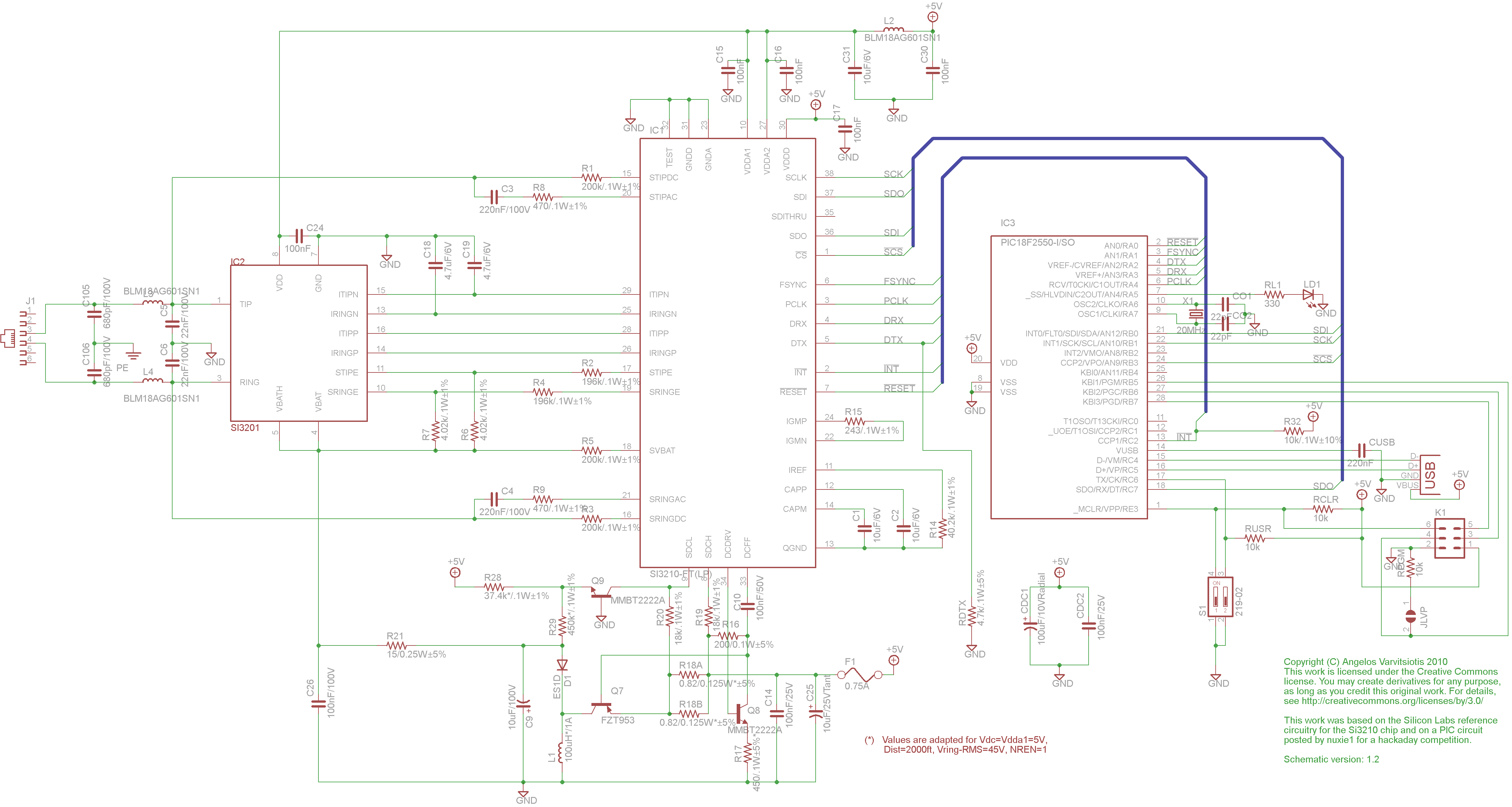
dyi setup and debugging guide
This page discusses the differences between assembled Open USB FXS dongle boards and DIY boards. While the assembled boards are fully tested and quality control approved, DIY boards may encounter various issues during assembly. Fortunately, most of these issues can...
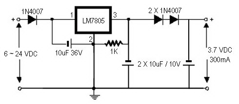
how to convert a 9v battery to 3.7v
A regulator circuit is needed for this DIY project. Familiarity with electronic components, circuitry, the use of a multitester, and a soldering iron is essential. The schematic diagram provided can accept an input voltage ranging from 6 to 24 volts...

turret diy
For maximum mini-security, this RC Tupperware Turret delivers a formidable deterrent against food theft. While it lacks motion sensors, potential food thieves will think twice before attempting to swipe baked goods. This 11-hour project, designed by Chris of PyroElectro, emphasizes...
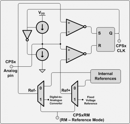
microcontroller 16f707 capacitive touch button
There are numerous applications for this hardware, including touch pads, proximity sensors, capacitive sensor readouts, high-precision capacitance measurements, ultra-small capacitance change detection, soil moisture sensing, and skin moisture measurement, among others. However, after searching for examples, it was surprising to...
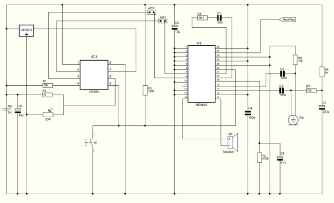
Halloween game with moving sensor (12F683)
Halloween is coming up and it's time to do some pranks. Everyone likes Halloween and I'm no exception. Every year me and my wife decorate the house with lots of bugs, spider webs, creepy posters and of course lots of...
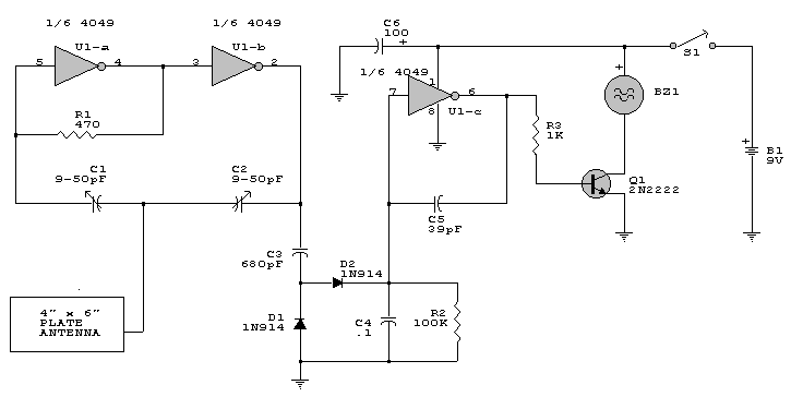
Simple Proximity Detector & Alarm Circuit
This is a simple proximity switch utilizing the IC 4049. The IC 4049 is a bipolar monolithic integrated circuit designed for metal detection systems and proximity sensing applications. It includes an oscillator formed by an external parallel resonant tank circuit...
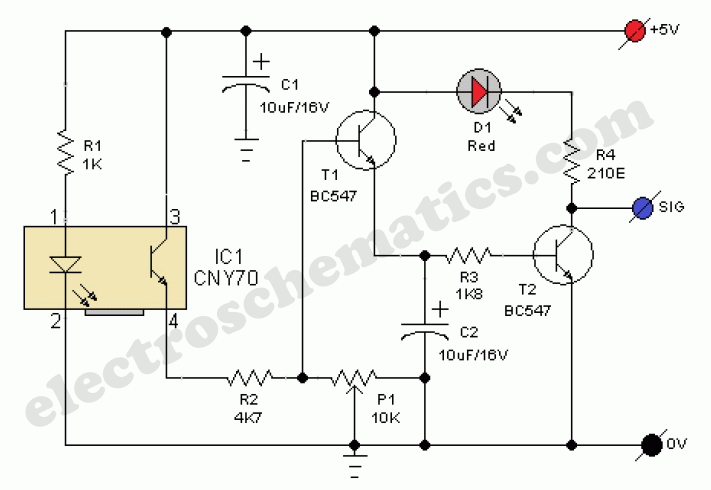
Proximity Sensor Circuit
This presence detector or proximity sensor circuit responds to the presence of any conductive object, including humans. The sensitivity can be adjusted with potentiometer P1, which is positioned at a considerable distance from the rest of the circuit. This circuit...
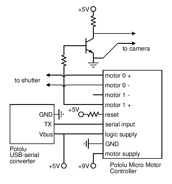
5 Minute Signal
For the past year and a half, a group based in Ann Arbor, Michigan, named GO-Tech has been formed, uniting individuals interested in creating projects using technology, such as hardware, software, metal, and wood. This initiative is referred to as...
Help with a schematic please
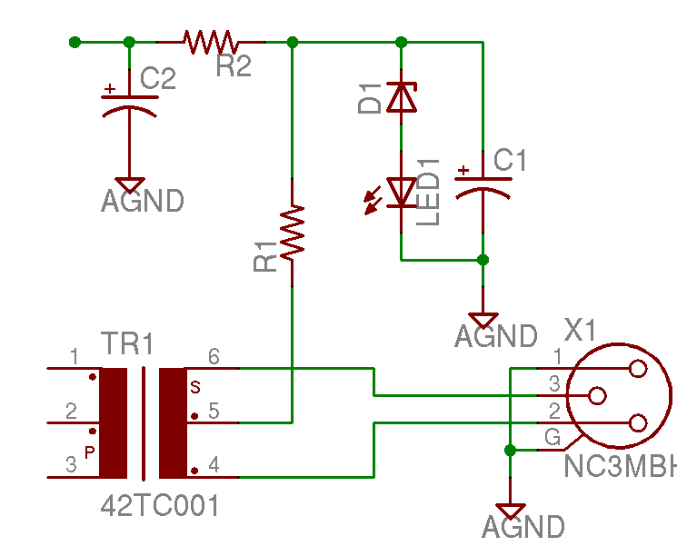
A project is underway to construct the CountryHick DI as illustrated on DIYFactory, incorporating a few minor modifications. The final design aims to be a 1U unit with four inputs.
The CountryHick DI (Direct Injection) box is a crucial tool in...