


Negative Ions Detector / Sensor
#ion detector
#negative ions
#sensor
#electrostatic charge
#air quality
#handheld device
#ion emissions
#static electricity
#electric field
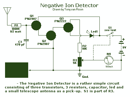
Description: Ions are defined as electrically charged atoms. Positively charged ions have a deficiency of electrons, and negatively charged ions have a surplus of electrons. An ion can also be classified as an atom or molecule with an electrostatic charge. Another classification of an ion is a charged particle that is formed when one or more electrons are taken from or added to a previously neutral atom or molecule. The Ion Detector described in this article can be used to detect the presence of free ions in the air. The Ion Detector, a handheld unit about the size of a pack of cigarettes, is designed to indicate ion emissions from Ion Generators, high-voltage leakage points, static-electricity sources, electric-field gradients, and in other situations where the presence of their relative flux density is required. The front cover features a sensitivity control with an on-off switch, a high flux indicator lamp, and a panel meter. An antenna, mounted on the top of the unit, serves as an external ion collector. A strip of metallic foil on the outside of the plastic enclosure touches the user's hand and is used to ground the unit. For fixed applications, the strip can be replaced by a wire connected to the ground. The Ion Detector consists of three transistors (two PN2907 PNP and a single PN2222 NPN type), three resistors, one capacitor, an antenna, a mA meter, and an LED. In that circuit, a telescoping antenna is used as the pickup. In the presence of an ion field, ions accumulate on the antenna, causing a minute negative current to flow to the base of Q1. Capacitor C1 and resistor R1 form an RC network, whose function is to eliminate any rapid fluctuations. Once the negative current becomes large enough, it causes Q1 to turn on, connecting the negative terminal of battery B1 to the base of Q2. That forward biases Q2, causing it to turn on. The detector is set up to detect negative ions. It can be made to detect positive ions by simply reversing the polarity of the transistors that comprise the circuit, i.e., PNP units become NPN units, and the NPN transistor is replaced by a PNP unit. The performance of the detector is seriously affected by high humidity. Damp or moist air tends to impair the circuit's ability to detect ion flux. That, in turn, couples the base of Q3 to the positive terminal of the battery, forward biases Q3 - whose collector is in series with current-limiting resistor R2 and meter-sensitivity control R3 - causing it to conduct.
The Ion Detector circuit operates by utilizing a combination of transistors to amplify the small current generated by ions accumulating on the antenna. The design is compact and portable, making it suitable for various applications, including environmental monitoring and safety assessments around high-voltage equipment.
The operational principle begins with the antenna, which captures free ions in the air. When ions accumulate on the antenna, they create a slight negative charge, generating a current that flows to the base of the first transistor (Q1). The choice of the PN2907 PNP transistor for Q1 is critical, as it allows the circuit to effectively respond to the negative charge. The RC network formed by capacitor C1 and resistor R1 plays a vital role in filtering out noise and ensuring that only significant ion-induced currents are detected.
Once the current reaches a threshold level, Q1 turns on, which in turn activates Q2. The activation of Q2 connects the battery's negative terminal to the next stage of the circuit, further amplifying the signal. This cascading effect of transistor action allows for sensitivity to low levels of ionization, making the device effective even in environments with minimal ion presence.
The circuit's flexibility is evident in its ability to switch between detecting negative and positive ions by simply changing the transistor configuration. This adaptability enhances its utility across different scenarios, such as in laboratories or industrial settings where both types of ions may need to be monitored.
The inclusion of a high flux indicator lamp and panel meter provides immediate visual feedback on ion concentration levels, allowing users to assess environmental conditions quickly. The sensitivity control enables users to adjust the threshold for detection, accommodating various atmospheric conditions and ensuring optimal performance.
Overall, the Ion Detector represents a practical solution for monitoring ion emissions, with a straightforward circuit design that balances sensitivity and user-friendliness, though it is important to consider environmental factors such as humidity that can influence its effectiveness.Ions are defined as electrically charged atoms. Positively charged ions have a deficiency of electrons, and negatively charged ions have a surplus of electrons. An ion can also be classified as an atom or molecule with an electrostatic charge. Another classification of an ion is a charged particle that is formed when one or more electrons are taken from or added to a previously neutral atom or molecule.
The Ion Detector described in this article can be used to detect the presence of free ions in the air. The Ion Detector, a handheld unit about the size of a pack of cigarettes, is designed to indicate ion emissions from Ion Generators, high-voltage leakage points, static-electricity sources, electric-field gradients, and in other situations where the presence of their relative flux density is required.
The front cover features, a sensitivity control with on-off switch, a high flux indicator lamp, and a panel meter. An antenna, mounted on the top of the unit, serves an external ion collector. A strip of metallic foil on the outside of the plastic enclosure touches the users hand and is used to ground the unit.
For fixed applications, the strip can be replaced by a wire connected to the ground. the Ion Detector--a rather simple circuit consisting of three transistors (two PN2907 PNP, and a single PN2222 NPN type), three resistors, one capacitor, an antenna, a mA meter, and an Led. In that circuit, a telescoping antenna is used as the pickup. In the presence of an ion field, ions accumulate on the antenna, causing a minute negative current to flow to the base of Q1.
Capacitor C1 and resistor R1 form an RC network, whose function is to eliminate any rapid fluctuations. Once the negative current becomes large enough, it causes Q1 to turn on, connecting the negative terminal of battery B1 to the base of Q2.
That forward biases Q2, causing it to turn on. The detector is set up to detect negative ions. It can be made to detect positive ions by simply reversing the polarity of the transistors that comprise the circuit, i.e., PNP units become NPN units, and NPN transistor is replaced by a PNP unit. I should note that the performance of the detector is seriously affected by high humidity. Damp or moist air tends to impair the circuits ability to detect ion flux. That, in turn, couples the base of Q3 to the positive terminal of the battery, forward biases Q3 - whose collector is in series with current-limiting resistor R2 and meter-sensitivity control R3 - causing it to conduct.
The Ion Detector circuit operates by utilizing a combination of transistors to amplify the small current generated by ions accumulating on the antenna. The design is compact and portable, making it suitable for various applications, including environmental monitoring and safety assessments around high-voltage equipment.
The operational principle begins with the antenna, which captures free ions in the air. When ions accumulate on the antenna, they create a slight negative charge, generating a current that flows to the base of the first transistor (Q1). The choice of the PN2907 PNP transistor for Q1 is critical, as it allows the circuit to effectively respond to the negative charge. The RC network formed by capacitor C1 and resistor R1 plays a vital role in filtering out noise and ensuring that only significant ion-induced currents are detected.
Once the current reaches a threshold level, Q1 turns on, which in turn activates Q2. The activation of Q2 connects the battery's negative terminal to the next stage of the circuit, further amplifying the signal. This cascading effect of transistor action allows for sensitivity to low levels of ionization, making the device effective even in environments with minimal ion presence.
The circuit's flexibility is evident in its ability to switch between detecting negative and positive ions by simply changing the transistor configuration. This adaptability enhances its utility across different scenarios, such as in laboratories or industrial settings where both types of ions may need to be monitored.
The inclusion of a high flux indicator lamp and panel meter provides immediate visual feedback on ion concentration levels, allowing users to assess environmental conditions quickly. The sensitivity control enables users to adjust the threshold for detection, accommodating various atmospheric conditions and ensuring optimal performance.
Overall, the Ion Detector represents a practical solution for monitoring ion emissions, with a straightforward circuit design that balances sensitivity and user-friendliness, though it is important to consider environmental factors such as humidity that can influence its effectiveness.Ions are defined as electrically charged atoms. Positively charged ions have a deficiency of electrons, and negatively charged ions have a surplus of electrons. An ion can also be classified as an atom or molecule with an electrostatic charge. Another classification of an ion is a charged particle that is formed when one or more electrons are taken from or added to a previously neutral atom or molecule.
The Ion Detector described in this article can be used to detect the presence of free ions in the air. The Ion Detector, a handheld unit about the size of a pack of cigarettes, is designed to indicate ion emissions from Ion Generators, high-voltage leakage points, static-electricity sources, electric-field gradients, and in other situations where the presence of their relative flux density is required.
The front cover features, a sensitivity control with on-off switch, a high flux indicator lamp, and a panel meter. An antenna, mounted on the top of the unit, serves an external ion collector. A strip of metallic foil on the outside of the plastic enclosure touches the users hand and is used to ground the unit.
For fixed applications, the strip can be replaced by a wire connected to the ground. the Ion Detector--a rather simple circuit consisting of three transistors (two PN2907 PNP, and a single PN2222 NPN type), three resistors, one capacitor, an antenna, a mA meter, and an Led. In that circuit, a telescoping antenna is used as the pickup. In the presence of an ion field, ions accumulate on the antenna, causing a minute negative current to flow to the base of Q1.
Capacitor C1 and resistor R1 form an RC network, whose function is to eliminate any rapid fluctuations. Once the negative current becomes large enough, it causes Q1 to turn on, connecting the negative terminal of battery B1 to the base of Q2.
That forward biases Q2, causing it to turn on. The detector is set up to detect negative ions. It can be made to detect positive ions by simply reversing the polarity of the transistors that comprise the circuit, i.e., PNP units become NPN units, and NPN transistor is replaced by a PNP unit. I should note that the performance of the detector is seriously affected by high humidity. Damp or moist air tends to impair the circuits ability to detect ion flux. That, in turn, couples the base of Q3 to the positive terminal of the battery, forward biases Q3 - whose collector is in series with current-limiting resistor R2 and meter-sensitivity control R3 - causing it to conduct.
Electric Field Mill Fabrication
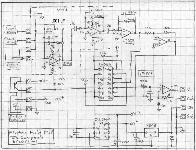
This page outlines the construction of an electric field mill, a device used to measure the electric field strength on Earth due to static electric fields and the charge of clouds overhead. It can also investigate the effects of static...
How to Shock People with Your Fingertips circuit
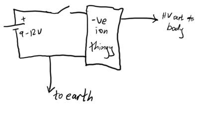
This article demonstrates how to create a simple yet effective static electricity generator. This device enables the user to carry a constant static charge on their body and discharge it onto anything grounded or of opposite polarity. The generated electricity...
Ion detector circuit diagram electronic project
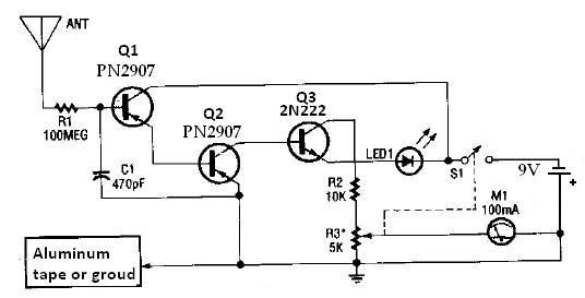
This ion detector circuit is designed to sense static charges and free ions present in the air. It is capable of detecting the presence of free ions, static electricity, or high voltage leakage. The project utilizes a short whip antenna,...
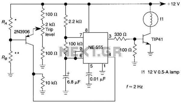
Sensor-Activated Relay Pulser Circuit
A sensor activates transistor Q1 to turn on the low-frequency 555 oscillator, which generates pulses to control LAMP II. The sensor may respond to variations in light or temperature. Either resistor RA or RB can function as the sensor, depending...
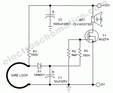
Wire Break Sensor Alarm Circuit Schematic
The circuit of a loop sensor-based simple security alarm is described here. The sensor loop consists of a short length of thin enamelled copper wire.
The loop sensor security alarm operates on the principle of detecting interruptions in the circuit formed...
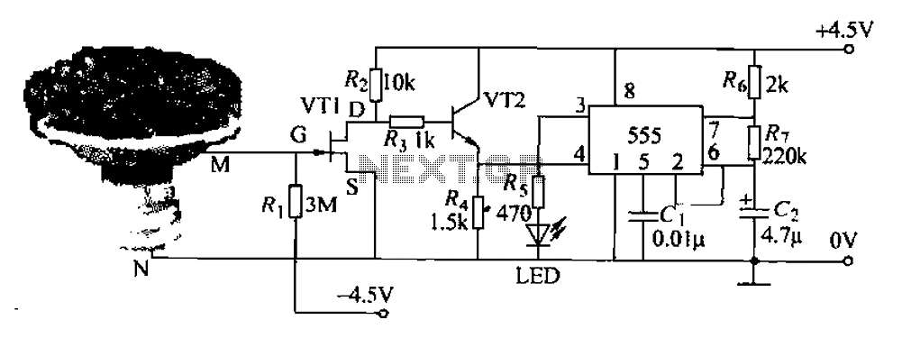
Pots water alarm circuit
The flowers in pots require watering, as relying solely on the observation of moist soil surfaces can be unreliable. To address this issue, a flower watering indicator has been developed. This circuit includes a field effect transistor (VT1), a second...
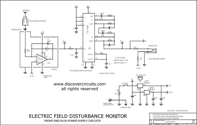
electric field disturbance
This schematic represents the power supply and front-end sections of the field monitor, which is further elaborated in the Electric Field Disturbance Monitor documentation. The system is capable of detecting human and animal motion through the electric fields they disrupt.
The...
AIR-FILTER SENSOR FOR HOME-USED AIR CONDITIONERS
This project involves the design of an air-filter sensor intended for use in home heating and cooling systems. The project encompasses conceptual design, analysis, implementation, testing, and modifications. Initially, the study focuses on comparing air quality and power consumption between...
Static Electricity / Negative Ion Detectors
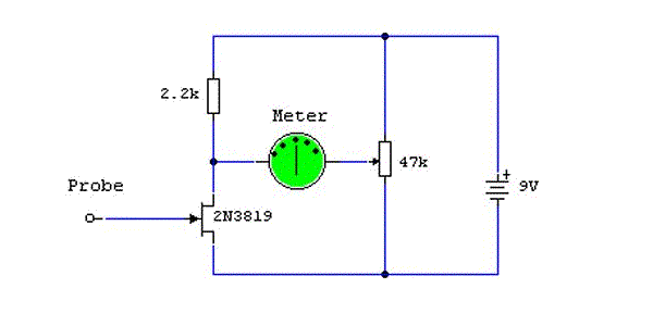
The sensitivity of the gate terminal to voltage changes is significant. In this configuration, the gate terminal is left open circuit and connected only to a probe, which consists of a few inches of bare copper wire. Without a fixed...