


One circuit thermistor relay contacts to prevent competition
#thermistor
#relay
#NTC
#delay switching
#contactor control
#temperature sensor
#circuit protection
#control systems
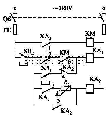
Description: Competition among relay contacts in contactor control systems often leads to significant issues that can be cumbersome to address. In some cases, this requires the addition of numerous components. However, utilizing a negative temperature coefficient thermistor (NTC) for delay switching can effectively mitigate relay contact competition. In Circuit 11, illustrated in FIG. 6, the thermistor resistance (RT) is higher at room temperature. After a delay period of approximately 0.5 seconds, the resistance sharply decreases, allowing the time delay relay (KA) to activate and prevent conflicts with the contactor (KM), thereby maintaining control of the circuit.
In this circuit design, the implementation of a negative temperature coefficient (NTC) thermistor serves as a crucial component for managing relay contact competition in contactor control systems. The NTC thermistor exhibits a high resistance at ambient temperatures, which allows for a gradual increase in current demand without immediate activation of the relay. This characteristic is essential for preventing simultaneous engagement of multiple relay contacts, which can lead to circuit instability or damage.
The operational sequence begins when power is applied to the circuit. Initially, the NTC thermistor maintains a high resistance, limiting the current flow to the downstream components. This delay period, typically set at around 0.5 seconds, is intentionally designed to allow the system to stabilize before any relay activation occurs. During this time, the thermistor's resistance begins to drop significantly as it heats up due to the flowing current.
Once the resistance of the NTC thermistor decreases sufficiently, it allows a higher current to flow through the circuit, activating the time delay relay (KA). This relay then engages the contactor (KM) to control the load. The precise timing of this activation is critical, as it ensures that the contactor is engaged only after the initial surge of current has passed, thus preventing any potential competition among the relay contacts.
The design also incorporates protective measures to ensure that the circuit remains stable and responsive under varying load conditions. By carefully selecting the specifications of the NTC thermistor and the time delay relay, the system can be tailored to meet specific operational requirements. Overall, this approach enhances the reliability and efficiency of contactor control systems by minimizing the risk of contact competition and ensuring smooth operation.Competition is ~ relay contacts contactor control systems often encounter problems, too much trouble to deal with, and sometimes need to add a lot of elements to add. However, if the use of negative temperature coefficient thermistor (NTC) delay switching characteristics, can easily and effectively prevent relay contact competition. Circuit 11 in FIG. 6. It is the thermistor resistance RT larger at room temperature, through the current demand after a period of delay (about 0. 5s), the sharp decline in the resistance, time delay relay KAz pull to avoid contact with the contactor KM point competition dispute, avoid circuit out of control.
In this circuit design, the implementation of a negative temperature coefficient (NTC) thermistor serves as a crucial component for managing relay contact competition in contactor control systems. The NTC thermistor exhibits a high resistance at ambient temperatures, which allows for a gradual increase in current demand without immediate activation of the relay. This characteristic is essential for preventing simultaneous engagement of multiple relay contacts, which can lead to circuit instability or damage.
The operational sequence begins when power is applied to the circuit. Initially, the NTC thermistor maintains a high resistance, limiting the current flow to the downstream components. This delay period, typically set at around 0.5 seconds, is intentionally designed to allow the system to stabilize before any relay activation occurs. During this time, the thermistor's resistance begins to drop significantly as it heats up due to the flowing current.
Once the resistance of the NTC thermistor decreases sufficiently, it allows a higher current to flow through the circuit, activating the time delay relay (KA). This relay then engages the contactor (KM) to control the load. The precise timing of this activation is critical, as it ensures that the contactor is engaged only after the initial surge of current has passed, thus preventing any potential competition among the relay contacts.
The design also incorporates protective measures to ensure that the circuit remains stable and responsive under varying load conditions. By carefully selecting the specifications of the NTC thermistor and the time delay relay, the system can be tailored to meet specific operational requirements. Overall, this approach enhances the reliability and efficiency of contactor control systems by minimizing the risk of contact competition and ensuring smooth operation.Competition is ~ relay contacts contactor control systems often encounter problems, too much trouble to deal with, and sometimes need to add a lot of elements to add. However, if the use of negative temperature coefficient thermistor (NTC) delay switching characteristics, can easily and effectively prevent relay contact competition. Circuit 11 in FIG. 6. It is the thermistor resistance RT larger at room temperature, through the current demand after a period of delay (about 0. 5s), the sharp decline in the resistance, time delay relay KAz pull to avoid contact with the contactor KM point competition dispute, avoid circuit out of control.
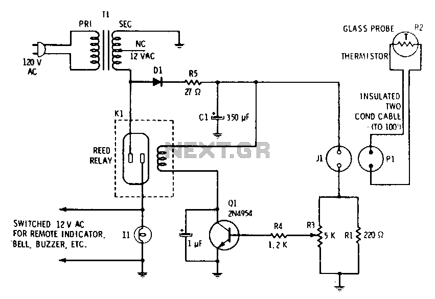
Flood-alarm-or-temperature-monitor
A filtered 15 V DC supply is applied to a series circuit that includes a thermistor (R2) and a parallel combination of resistors (R1 and R3). The transistor (Q1) functions as a switch, with its state controlled by the setting...
Coffee thermometer circuit
Measuring the temperature of coffee is important because the taste of coffee relies on two main factors: the strength of the coffee and its temperature.
Measuring the temperature of coffee can be accomplished using a simple electronic circuit designed to provide...
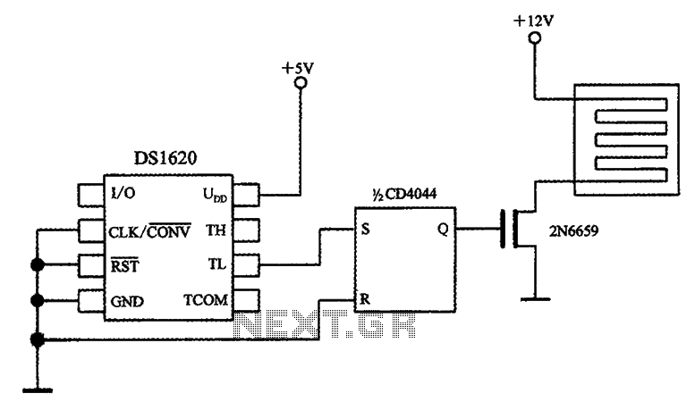
Temperature control circuit diagram with three-wire serial interface smart temperature sensors DS1620
The circuit involves a smart temperature control system utilizing DS1620 temperature sensors with a three-wire serial interface for managing a small electric heater. When the CD4044 type RS flip-flop is set to 1, the output Q becomes high, which activates...
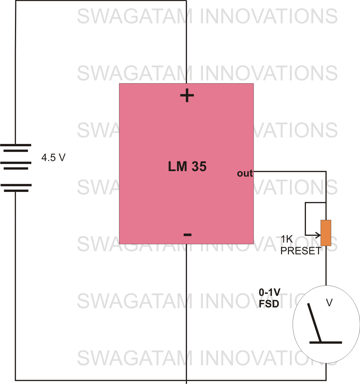
making simplest room thermometer
The circuit diagram provided illustrates a straightforward setup. There is no requirement for complex circuitry; simply connect a 0-1 V full-scale deflection (FSD) moving coil meter across the designated pins of the integrated circuit (IC). Adjust the potentiometer as needed,...
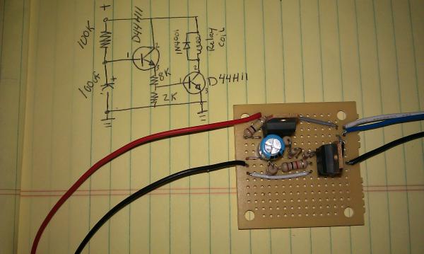
Homemade tablet CarPC
The momentary hold relay board and the accessory delay module are components designed for automotive applications. The momentary hold relay board powers the GPS unit and the tablet, eliminating the need for manual button activation. The accessory delay module is...
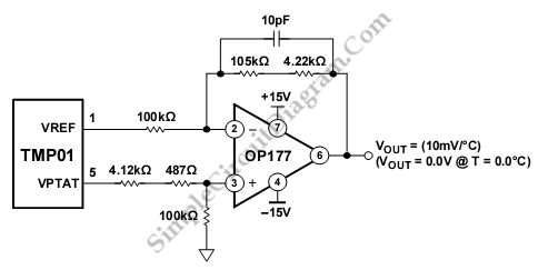
TMP01 Celsius Scale Temperature Sensor
The schematic diagram described here is a TMP01 Celsius Scale Temperature Sensor circuit. This circuit is used to convert the VPTAT output voltage.
The TMP01 is a temperature sensor integrated circuit designed to provide an accurate temperature measurement in Celsius. It...
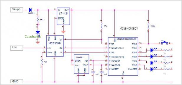
Lin Temperature Sensor Using The Mc68hc908qt/qy Mcu
The LinkSwitch-LP family is designed to replace inefficient line frequency linear transformer-based power supplies with output powers less than 2.5 W in applications such as cell/cordless phones, PDAs, digital cameras, and portable audio players. LinkSwitch-LP may also be used as...
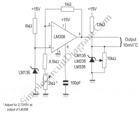
LM135/235/335 Centigrade Thermometer
The LM135/235/335 temperature sensor is designed for ease of absolute temperature reading, providing all positive values for any frequency. This is why a voltage of 2.7315V is observed at 0 degrees.
The LM135/235/335 series of temperature sensors are precision devices that...
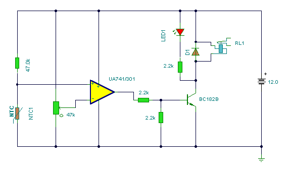
Temperature Monitors
A thermistor positioned as indicated creates a heat-activated sensor. Variations in temperature will modify the output of the operational amplifier, activating the relay and illuminating the LED. Interchanging the positions of the thermistor and the 47k resistor transforms the circuit...