


Ultrasonic Range Sensor
#ultrasonic
#range sensor
#microcontroller
#40KHz
#Panasonic
#bridge rectifier
#voltage regulator
#RCX
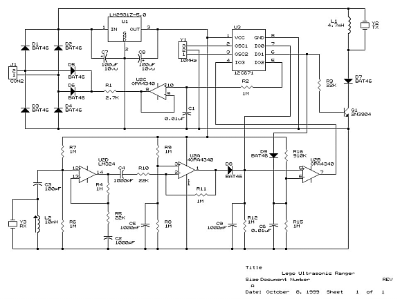
Description: The Panasonic transducers are no longer available, but the design remains interesting as an example. J1 connects to the RCX. D1 to D4 create a bridge rectifier to obtain local power from the RCX, which is stored on C7 and regulated to 5V by U1, a low power, low dropout regulator. The microcontroller, U3, is programmed to generate a burst of 8 x 40KHz pulses on pin 6. Q1 switches current into L1, creating a "flyback" voltage output to Y2, the ultrasonic transmitter, of approximately 20V peak. The 40KHz frequency is derived from a software division of the 10MHz reference (the ceramic resonator, Y1, in this case). Y3, the ultrasonic receiver, is band-limited by L2 to prevent normal sound and vehicle vibrations from becoming the dominant input. L2 is selected to form a resonant circuit with the self-capacitance of the receiver piezo, peaking at 40KHz. U2D and U2A serve as the primary gain stages, amplifying the millivolt-level signals to a couple of volts. Using a rail-to-rail amplifier with symmetrical (1/2 rail) biasing enhances overload recovery efficiency for large input overloads from highly reflective targets. D8 rectifies the returns onto C9. D9 generates an exponential waveform on C6 driven by the initial pulse burst, forming a comparison input to U2B, which outputs a logic "1" whenever a return exceeds a range-sensitive threshold. This design focuses only on the first return (the closest object), as the RCX cannot process a series of returns from different ranges. Both analog and logic-level returns are fed into the microcontroller via analog input pin 7 and digital input pin 4. The current firmware utilizes only the logic input. The microcontroller times the returns and converts them into a varying mark/space square wave on digital output pin 5. This square wave is converted to a voltage on C1 and presented to the RCX analog input through R1 and D5/D6 during the RCX's analog sample time. Notably, the diodes are Schottky types to minimize voltage drop, especially in the bridge. The circuit is designed around a limited range of resistors and capacitors to reduce inventory requirements. Other sensors in development utilize these same values where feasible. There is a transmit overload recovery time of approximately 6 inches, primarily due to mechanical resonance in the mounting of Y2 and Y3. The average bump sensor should detect any object within 6 inches if the ultrasonic ranger is positioned centrally on top of the robot. This was classified as a category 5 project, requiring significant effort to fit the components into the desired enclosure. The construction utilized perforated prototype board, with one pad per hole type. The device was compacted into a smaller battery holder by removing the battery clips and switch mechanism, with the outer part of the switch glued back for cosmetic purposes. A challenge arose from using the battery box, as the bus strips generated considerable switching noise from the RCX's multiplexed power scheme, which was picked up by the input amplifier. To mitigate this, the bus strip was severed so that only the end four power studs were used (the ones furthest from the receiver piezo and input amplifier section). The remaining bus strips were covered with grounded self-adhesive copper foil for shielding, followed by a layer of PVC tape to prevent shorting any components.
This circuit design illustrates a sophisticated approach to ultrasonic sensing, utilizing a microcontroller to manage signal processing and amplification while ensuring efficient power management through a bridge rectifier and low dropout regulator. The architecture includes critical components such as a ceramic resonator for frequency stability and a piezoelectric transducer for both transmission and reception of ultrasonic waves. The design's focus on minimizing noise and maximizing sensitivity is evident in the choice of Schottky diodes and the careful arrangement of components to avoid interference. The implementation of resonant circuits to optimize signal capture further enhances the system's performance, enabling effective distance measurement in robotic applications. The compact construction and thoughtful shielding solutions demonstrate practical engineering considerations in overcoming challenges associated with component integration and environmental noise. Overall, this circuit serves as a valuable reference for ultrasonic sensor design in embedded systems, showcasing effective techniques for signal processing and power management in compact electronic devices.The Panasonic transducers are no longer available, but the design is still interesting as an example. J1 is the connection to the RCX. D1 - D4 form a bridge rectifier to obtain local power from the RCX which is stored on C7 and regulated to 5V by U1, a low power, low dropout regulator.
The microcontroller, U3 is programmed to generate a burst of 8 x 40KHz pulses on pin 6. Q1 switches current into L1 creating a "flyback" voltage output to Y2, the ultrasonic transmitter, of about 20V peak. The 40KHz is based on a software division of the 10MHz reference (the ceramic resonator, Y1, in this case). Y3, the ultrasonic receiver, is band-limited by L2, to stop normal sound and vehicle vibration from being the dominant input.
L2 is chosen to form a resonant circuit with the self capacitance of the receiver piezo. It should be peaked for 40KHz. U2D and U2A are the primary gain stages to get the millivolt level signals up to a couple of volts. Use of a rail to rail amplifier with symmetrical (1/2 rail) biasing makes overload recovery very efficient for large input overloads from very reflective targets. D8 rectifies the returns on C9. D9 generates a exponential waveform on C6 driven from the initial pulse burst. This forms a comparison input to U2B which outputs a logic "1" whenever a return exceeds a range sensitive threshold.
This design is only interested in the first return (closest object) since the RCX cannot handle a series of returns from different ranges. Both the analog and logic level returns are input to the microcontroller via analog input pin 7 and digital input pin 4.
The current firmware only makes use of the logic input. The microcontroller times the returns and converts them into a varying mark/space squarewave on digital output pin 5. This squarewave is converted to a voltage on C1 and presented to the RCX analog input via R1 and D5/D6 during the RCX`s analog sample time.
Note. The diodes are schottky types to minimize voltage drop, particularly in the bridge. I would be happy to program a 12C671 for anyone interested. I have designed this circuit around a limited range of Rs and Cs to minimize inventory requirements. Other sensors I`m working on use these same values where possible. There is a transmit overload recovery time equivalent to about 6 inches. This seems to be mainly due to mechanical resonance in the mounting of Y2 and Y3. (The average bump sensor should catch anything within 6 inches if the ultrasonic ranger is placed centrally on top of the robot!) This was a category 5 project. Hard work to get the parts into the desired enclosure. I used perforated prototype board, one pad per hole type for the construction. I squeezed this device into the smaller size battery holder. Simply remove the battery clips and switch mechanism. I glued the outer part of the switch back in place for cosmetic reasons. I had one problem with using the battery box. The buss strips radiate a lot of switching noise, from the RCX`s multiplexed power scheme, which is picked up by the input amplifier.
I severed the buss strip so that only the end four power studs are used (the ones furthest from the receiver piezo and input amplifier section. I covered the rest of the buss strips with grounded self adhesive copper foil to act as shielding, followed by a layer of pvc tape to avoid shorting any of the components.
This circuit design illustrates a sophisticated approach to ultrasonic sensing, utilizing a microcontroller to manage signal processing and amplification while ensuring efficient power management through a bridge rectifier and low dropout regulator. The architecture includes critical components such as a ceramic resonator for frequency stability and a piezoelectric transducer for both transmission and reception of ultrasonic waves. The design's focus on minimizing noise and maximizing sensitivity is evident in the choice of Schottky diodes and the careful arrangement of components to avoid interference. The implementation of resonant circuits to optimize signal capture further enhances the system's performance, enabling effective distance measurement in robotic applications. The compact construction and thoughtful shielding solutions demonstrate practical engineering considerations in overcoming challenges associated with component integration and environmental noise. Overall, this circuit serves as a valuable reference for ultrasonic sensor design in embedded systems, showcasing effective techniques for signal processing and power management in compact electronic devices.The Panasonic transducers are no longer available, but the design is still interesting as an example. J1 is the connection to the RCX. D1 - D4 form a bridge rectifier to obtain local power from the RCX which is stored on C7 and regulated to 5V by U1, a low power, low dropout regulator.
The microcontroller, U3 is programmed to generate a burst of 8 x 40KHz pulses on pin 6. Q1 switches current into L1 creating a "flyback" voltage output to Y2, the ultrasonic transmitter, of about 20V peak. The 40KHz is based on a software division of the 10MHz reference (the ceramic resonator, Y1, in this case). Y3, the ultrasonic receiver, is band-limited by L2, to stop normal sound and vehicle vibration from being the dominant input.
L2 is chosen to form a resonant circuit with the self capacitance of the receiver piezo. It should be peaked for 40KHz. U2D and U2A are the primary gain stages to get the millivolt level signals up to a couple of volts. Use of a rail to rail amplifier with symmetrical (1/2 rail) biasing makes overload recovery very efficient for large input overloads from very reflective targets. D8 rectifies the returns on C9. D9 generates a exponential waveform on C6 driven from the initial pulse burst. This forms a comparison input to U2B which outputs a logic "1" whenever a return exceeds a range sensitive threshold.
This design is only interested in the first return (closest object) since the RCX cannot handle a series of returns from different ranges. Both the analog and logic level returns are input to the microcontroller via analog input pin 7 and digital input pin 4.
The current firmware only makes use of the logic input. The microcontroller times the returns and converts them into a varying mark/space squarewave on digital output pin 5. This squarewave is converted to a voltage on C1 and presented to the RCX analog input via R1 and D5/D6 during the RCX`s analog sample time.
Note. The diodes are schottky types to minimize voltage drop, particularly in the bridge. I would be happy to program a 12C671 for anyone interested. I have designed this circuit around a limited range of Rs and Cs to minimize inventory requirements. Other sensors I`m working on use these same values where possible. There is a transmit overload recovery time equivalent to about 6 inches. This seems to be mainly due to mechanical resonance in the mounting of Y2 and Y3. (The average bump sensor should catch anything within 6 inches if the ultrasonic ranger is placed centrally on top of the robot!) This was a category 5 project. Hard work to get the parts into the desired enclosure. I used perforated prototype board, one pad per hole type for the construction. I squeezed this device into the smaller size battery holder. Simply remove the battery clips and switch mechanism. I glued the outer part of the switch back in place for cosmetic reasons. I had one problem with using the battery box. The buss strips radiate a lot of switching noise, from the RCX`s multiplexed power scheme, which is picked up by the input amplifier.
I severed the buss strip so that only the end four power studs are used (the ones furthest from the receiver piezo and input amplifier section. I covered the rest of the buss strips with grounded self adhesive copper foil to act as shielding, followed by a layer of pvc tape to avoid shorting any of the components.
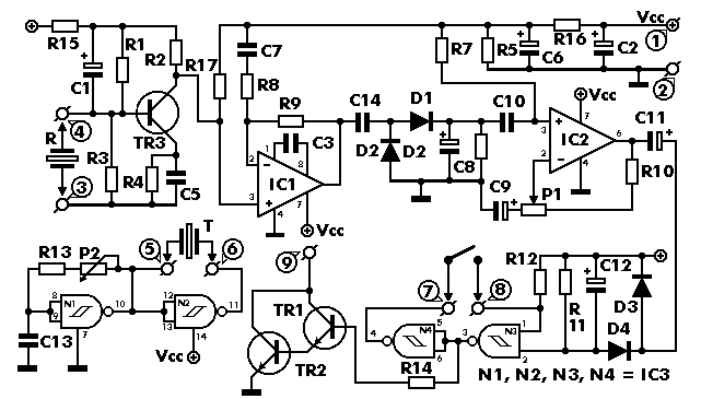
UltraSonic Radars
This project has numerous practical applications in security and alarm systems for homes, shops, and vehicles. It features a set of ultrasonic transmitter and receiver operating at the same frequency. When an object moves within the area covered by the...
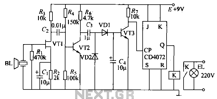
Ultrasonic remote control switch lighting circuit
The T-40-16 and 555 ultrasonic transmitter circuit configuration consists of an ultrasonic transmitter T-40-16 and a 555 timer circuit. By adjusting the potentiometer RP, the oscillation frequency of the circuit can be changed. The output pulse frequency from the 555...
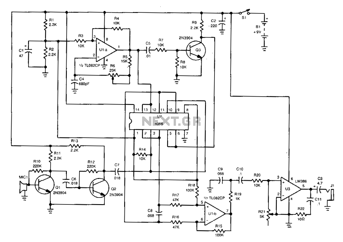
Ultrasonic-receiver
The piezo speaker, MIC1, detects the incoming ultrasonic signal and transmits it to the base of Q1. A two-transistor booster amplifier composed of Q1 and Q2 amplifies the signal to a level adequate for driving one input of this unique...
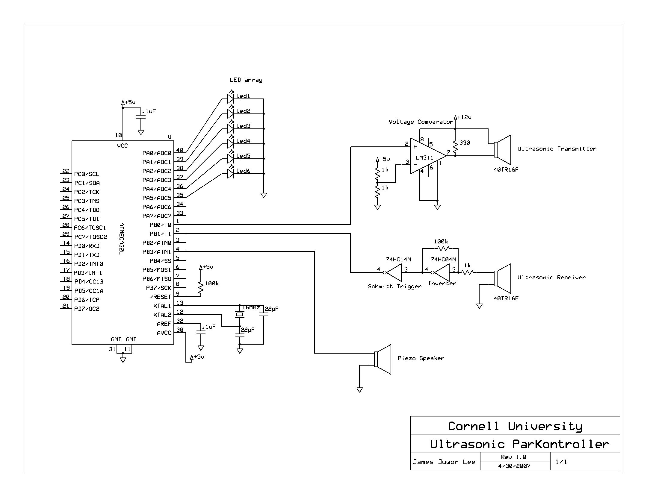
Ultrasonic Parking controller
A series of five short pulses blasted by the microcontroller only has 5V amplitude, which will be attenuated down to less than 20 mV when received by the receiver circuit. Hence, LM311 voltage comparator was used for signal amplification before...
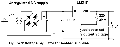
Regulator Combination Circuits
There are a number of ways to obtain the low voltages required to run small projects from the wall power outlet. The simplest way is to buy a factory-built molded supply which is designed to plug directly into the wall...
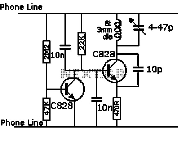
ultrasonic measurement circuit
This design circuit is for an electrostatic transducer used in ultrasonic measurement applications. It employs the LM1812 ultrasonic transceiver. The transducer (X1) and the LM1812 work together to transmit a burst of oscillations. The return echo is detected by X1,...
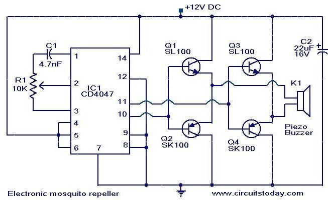
Electronic mosquito repeller
The circuit diagram of an ultrasonic mosquito repeller is based on the principle that insects, such as mosquitoes, can be repelled using sound frequencies in the ultrasonic range (above 20 kHz). The circuit utilizes a CMOS 4047 PLL IC configured...
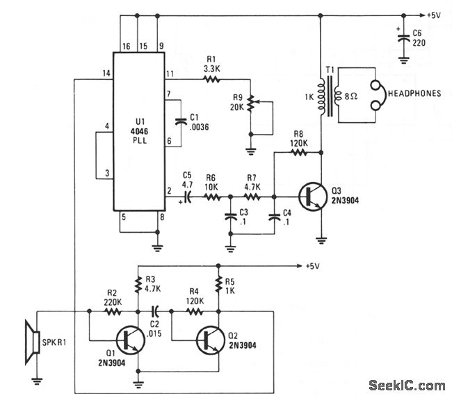
ULTRASONIC RECEIVER
The 4046 PLL serves as the core component of a tunable ultrasonic receiver designed to detect inaudible ultrasonic sounds. This receiver can also be utilized in conjunction with a basic ultrasonic generator to transmit and receive Morse code. The ultrasonic...

12V DC Dual Power Supply Circuit with IC 7812&7912
The 78W series voltage regulators are designed to handle an input voltage of approximately 35V, while the 24V type can withstand up to 40V. It should be noted that these regulators will not operate effectively with a significant input-output voltage...