


A touch-AC electronic switching circuit
#touch switch
#transistor amplifier
#trigger circuit
#electronic switching
#rectifier
#filter
#capacitance
#AC
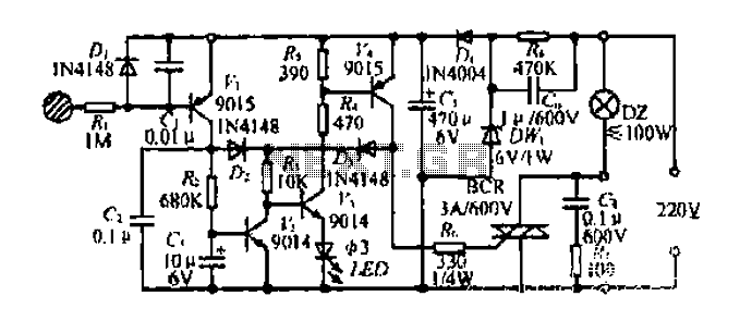
Description: Diagram 2 depicts a shake tube circuit with a capacitance (C) and a trigger voltage rectifier filter element. The circuit includes a trigger voltage transistor amplifier (H), three pull tubes (n, U, v), and utilizes a thyristor as a BCR diac. An LED is used to indicate the switching status, and additional components include a capacitor (C6) and a power circuit section (DW). When the touch-sensitive sheet is briefly activated by a finger, the body's AC induction voltage is rectified through a diode, and the capacitor (C) filters the voltage to produce a pulsating DC voltage. This voltage is input to the base of a transistor (H), causing it to conduct. The circuit allows for two paths of electrode current; one path flows to the base of transistor (V2), which results in a short collector current that does not significantly alter the voltage across capacitor (C). The other path involves components (R, U, G), allowing collector current to flow through the base of transistor (n), switching it from an off state to a saturated conduction state, supplying nearly 6V. This enables current to flow through the SCR system, turning on the light bulb (DZ). When the high potential electrode (V-ju) maintains current through the island, it keeps the base of transistor (U) in a saturated conduction state. To turn off the power, a longer touch (over 3 seconds) causes the collector current to flow through resistor (Rz), charging capacitor (C3). Once capacitor (C3) charges to 0.7V, the transistor (n) turns off, leading to a low potential at (V4) and cutting off the gate current of the thyristor (BCR), turning off the light bulb (DZ). After the touch is released, transistors (U, V) remain in the off state.
The circuit described operates as a touch-sensitive switch utilizing both capacitive sensing and transistor amplification. The initial touch triggers the rectification of AC voltage induced by the human body, which is then filtered to produce a usable DC voltage. The transistor amplifier (H) plays a crucial role in amplifying the input signal, allowing for reliable triggering of subsequent components.
The two paths for the electrode current serve to control the state of the transistors in a manner that is responsive to the duration of the touch. The design ensures that a brief touch does not significantly impact the capacitor's voltage, preventing unwanted triggering of the thyristor. In contrast, a prolonged touch allows for sufficient current to flow through the charging resistor (Rz), enabling the capacitor (C3) to reach the threshold voltage necessary to deactivate the transistor (n) and thus the thyristor (BCR), resulting in the light bulb (DZ) turning off.
The use of a thyristor as a BCR diac in this circuit is particularly effective for controlling high-power loads, as it can handle significant currents while remaining in a stable state once triggered. The LED indicator provides visual feedback on the operational status of the circuit, enhancing user interaction. Overall, this circuit design illustrates an efficient method of interfacing human touch with electronic control systems, suitable for applications in automation and remote control.Diagram 2 shake tube n. Capacitance C. Trigger voltage rectifier filter element. H is a trigger voltage transistor amplifier circuit, three pull tube n, U, v. Composition trigg er thyristor as BCR diac. LED switching status display, c6. G. day. DW, dish for the power circuit section. When touched with a finger briefly under speculation inch touch sheet, the bodys AC induction voltage through the diode rectifier, capacitor c, filter plus obtain a pulsating DC voltage, input A transistor base so conduction, H set an electrode current two routes, all the way to the flow of R.V2 base because it is a short touch, so collector current is short, the current does not cause C, the voltage changed greatly .K not turned on, and the other JL! stream troops, R, U G pole, so n will have collector current flowing through the n base, so n.V4 from off state into saturated conduction state exhausted, the n-nest high electrode electrically him (nearly 6V supply voltage).
the a current through the SCR system very romantic person, SCR BCR conducting open shoulder .DZ light bulb. and when the high potential electrode V-ju, will maintain the current through the island, K3 inflows U base, maintain U.
the V4 saturated conduction state. to turn off power to the switch, just simply touching a finger again to bring films, Rang contact time is more than 3 seconds, so collector electrode has a longer duration of current flows through Rz charge to C3, when the white charging to 0.7V, n is turned off and the n low potential, V4 also turned off thyristor gate current losing BCR cut LL.DZ lamp goes out. after touch-up, U, V held in the off state.
The circuit described operates as a touch-sensitive switch utilizing both capacitive sensing and transistor amplification. The initial touch triggers the rectification of AC voltage induced by the human body, which is then filtered to produce a usable DC voltage. The transistor amplifier (H) plays a crucial role in amplifying the input signal, allowing for reliable triggering of subsequent components.
The two paths for the electrode current serve to control the state of the transistors in a manner that is responsive to the duration of the touch. The design ensures that a brief touch does not significantly impact the capacitor's voltage, preventing unwanted triggering of the thyristor. In contrast, a prolonged touch allows for sufficient current to flow through the charging resistor (Rz), enabling the capacitor (C3) to reach the threshold voltage necessary to deactivate the transistor (n) and thus the thyristor (BCR), resulting in the light bulb (DZ) turning off.
The use of a thyristor as a BCR diac in this circuit is particularly effective for controlling high-power loads, as it can handle significant currents while remaining in a stable state once triggered. The LED indicator provides visual feedback on the operational status of the circuit, enhancing user interaction. Overall, this circuit design illustrates an efficient method of interfacing human touch with electronic control systems, suitable for applications in automation and remote control.Diagram 2 shake tube n. Capacitance C. Trigger voltage rectifier filter element. H is a trigger voltage transistor amplifier circuit, three pull tube n, U, v. Composition trigg er thyristor as BCR diac. LED switching status display, c6. G. day. DW, dish for the power circuit section. When touched with a finger briefly under speculation inch touch sheet, the bodys AC induction voltage through the diode rectifier, capacitor c, filter plus obtain a pulsating DC voltage, input A transistor base so conduction, H set an electrode current two routes, all the way to the flow of R.V2 base because it is a short touch, so collector current is short, the current does not cause C, the voltage changed greatly .K not turned on, and the other JL! stream troops, R, U G pole, so n will have collector current flowing through the n base, so n.V4 from off state into saturated conduction state exhausted, the n-nest high electrode electrically him (nearly 6V supply voltage).
the a current through the SCR system very romantic person, SCR BCR conducting open shoulder .DZ light bulb. and when the high potential electrode V-ju, will maintain the current through the island, K3 inflows U base, maintain U.
the V4 saturated conduction state. to turn off power to the switch, just simply touching a finger again to bring films, Rang contact time is more than 3 seconds, so collector electrode has a longer duration of current flows through Rz charge to C3, when the white charging to 0.7V, n is turned off and the n low potential, V4 also turned off thyristor gate current losing BCR cut LL.DZ lamp goes out. after touch-up, U, V held in the off state.
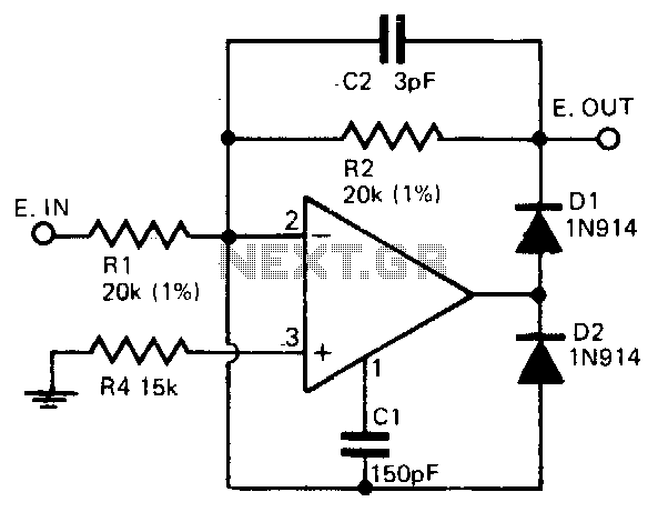
Fast half-wave rectifier
A precision half-wave rectifier utilizing an operational amplifier will achieve a rectification accuracy of 1% from DC to 100 kHz.
A precision half-wave rectifier circuit is designed to convert an AC signal into a unidirectional output while maintaining high accuracy in...
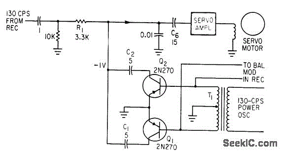
SYNCHRONOUS FILTER FOR ADF
Separates 130-cps motor drive voltage from voice frequencies in the output of an ADF receiver. P. V. Sparks, Servo Filter and Gain Control Improve Automatic Direction Finder, Electronics, 34:23, p 110-113.
The circuit described functions as a filter that effectively separates...
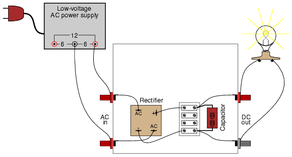
Rectifier/filter circuit Semiconductors
A bridge rectifier module is strongly recommended over building a bridge rectifier circuit using individual diodes. These modules are designed to be mounted on a metal heat sink. A metal enclosure is preferred over a plastic one due to its...
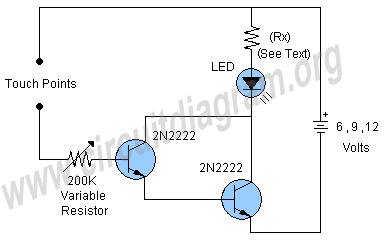
simple touch switch circuit
This project involves a simple touch switch circuit that can also be utilized to activate a relay instead of an LED and resistor. The circuit exhibits high sensitivity due to the use of two transistors configured as a Darlington pair....
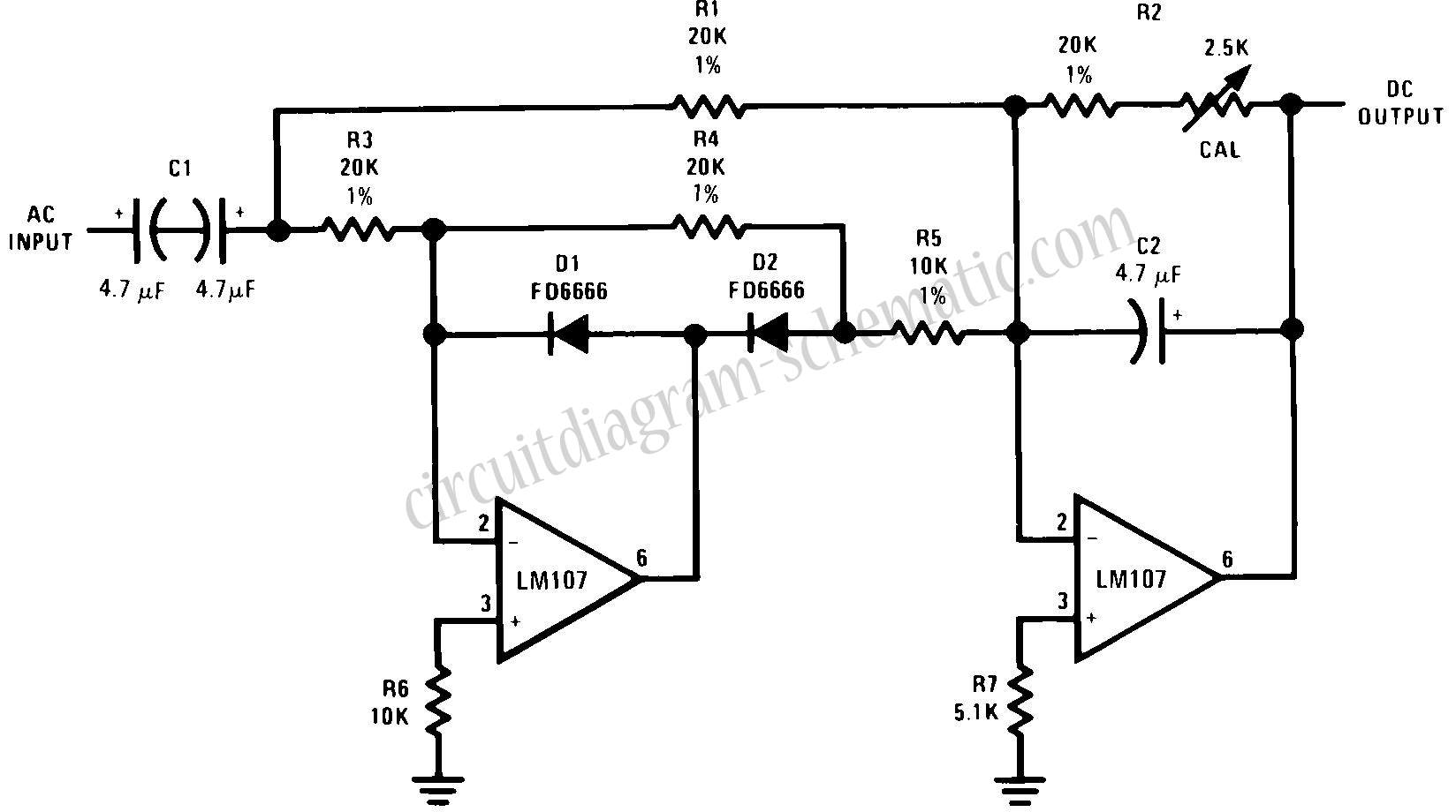
Full Wave Rectifier Circuit with Averaging Filter
This circuit is an RMS-calibrated AC voltmeter that provides average readings. Removing capacitor C2 eliminates the averaging function, resulting in a precision full-wave rectifier, while removing capacitor C1 transforms the circuit into an absolute value generator. The operation of the...
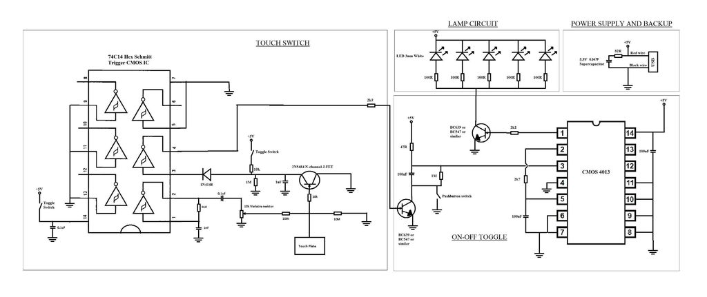
Touch switch circuit
A touch switch for a USB-powered desk lamp is malfunctioning. The circuit diagram, layout, and pictures are provided below. The design incorporates circuits sourced from two websites, specifically the fourth circuit. The output of the touch switch is connected to...
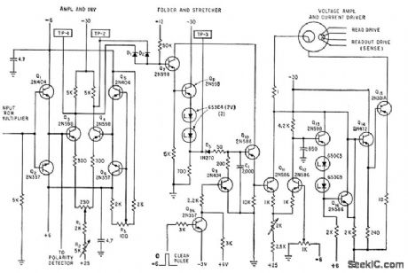
ROTARY SWITCH DEBOUNCE
A three-stage active Butterworth bandpass input filter is utilized in a radioteletype demodulator to differentiate RTTY tones from one another and from noise. The filter is centered at 2200 Hz and has a bandwidth of approximately 260 Hz, allowing for...
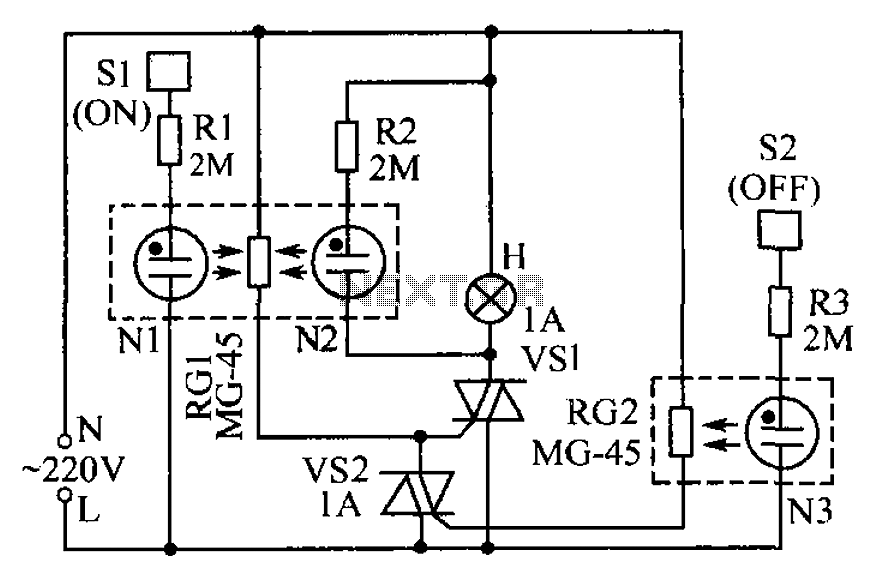
Lamp touch switch circuit diagram
The circuit operates based on the principle that neon tubes N1, N2, and the photosensitive resistor RG1 form an optocoupler. When a finger touches the metal sheet S1, N1 lights up, causing RG1's resistance to decrease. This reduction allows the...
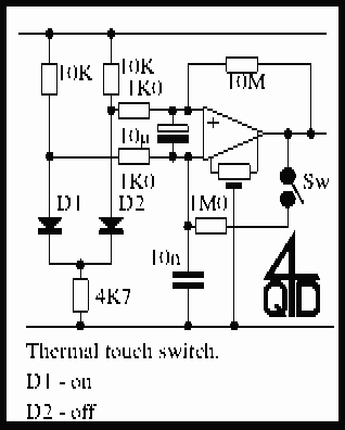
Touch Switches Collection
Touch operated switches are an attractive project for DIY electronics but they are not so common in commercial products. The reason for this is that, although there are many different ways of implementing a touch switch (leakage, hum pickup, capacitance,...