


AC contactor DC capacitive circuit a run
#AC contactor
#DC excitation
#power consumption
#electromagnet
#capacitive circuit
#energy efficiency
#electrical switching
#circuit optimization
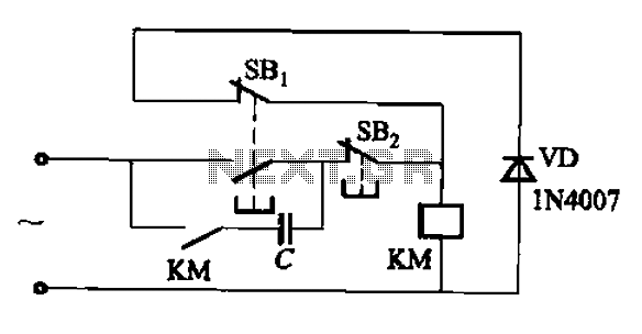
Description: An AC contactor switch, when used with DC or pulse DC excitation, can minimize short circuit and core power consumption. This results in a significant reduction in the power consumption of the electromagnet, which can eliminate noise and reduce the temperature rise of the coil, thereby extending its lifespan. The AC contactor DC capacitive circuit can operate in various configurations. Typically, the capacitance (C) ranges from 1 to 6 microfarads (µF) at a voltage rating of 630V, while the resistance (R) usually falls between 5.1 and 27 ohms, with a power rating of 10 to 30 watts. The contact capacity indicates that a larger capacitance (C) correlates with a smaller resistance (R), although this results in higher power consumption.
The AC contactor switch operates by controlling the flow of electrical current in an AC circuit, utilizing DC or pulse DC excitation to enhance efficiency. The incorporation of DC excitation allows for a reduction in the overall energy consumed by the electromagnet, which is critical in applications requiring prolonged operation. The reduction in power consumption is achieved through the elimination of short circuit effects and core losses, which are prevalent in traditional AC systems.
The design of the AC contactor DC capacitive circuit involves several key components, including the contactor itself, capacitors, and resistors. The capacitors serve to store electrical energy, while the resistors help to limit the current flow and manage the thermal characteristics of the circuit. The specified capacitance range of 1 to 6 µF is suitable for various operational scenarios, providing flexibility in circuit design. The resistance values, ranging from 5.1 to 27 ohms, are essential for optimizing the performance of the circuit, as they influence the current draw and heat generation within the system.
Furthermore, the relationship between capacitance and resistance is critical for determining the efficiency of the contactor circuit. A higher capacitance allows for greater energy storage, which can be advantageous in applications that require rapid switching or high inrush currents. However, this must be balanced against the resistance, as lower resistance values can lead to increased power consumption, necessitating careful consideration during design.
Overall, the implementation of an AC contactor switch with DC excitation presents a viable solution for reducing power consumption, noise, and thermal buildup, thus enhancing the longevity and reliability of electromagnetic systems.AC contactor switch to DC or pulse DC excitation can subtract short ring and core power consumption, thereby greatly reducing the power consumption of the electromagnet, and ca n eliminate the noise, but also can reduce the temperature rise of the coil, extending its life. AC contactor DC capacitive circuit has run a variety of types, as shown in FIG. C- capacitance is generally 1 ~ 6 TJ, F, 630V, R- resistance is generally 5.1 ~ 27fl, 10 ~ 30W. Contact capacity, the greater the capacity C, R resistance is smaller, but the greater the power.
The AC contactor switch operates by controlling the flow of electrical current in an AC circuit, utilizing DC or pulse DC excitation to enhance efficiency. The incorporation of DC excitation allows for a reduction in the overall energy consumed by the electromagnet, which is critical in applications requiring prolonged operation. The reduction in power consumption is achieved through the elimination of short circuit effects and core losses, which are prevalent in traditional AC systems.
The design of the AC contactor DC capacitive circuit involves several key components, including the contactor itself, capacitors, and resistors. The capacitors serve to store electrical energy, while the resistors help to limit the current flow and manage the thermal characteristics of the circuit. The specified capacitance range of 1 to 6 µF is suitable for various operational scenarios, providing flexibility in circuit design. The resistance values, ranging from 5.1 to 27 ohms, are essential for optimizing the performance of the circuit, as they influence the current draw and heat generation within the system.
Furthermore, the relationship between capacitance and resistance is critical for determining the efficiency of the contactor circuit. A higher capacitance allows for greater energy storage, which can be advantageous in applications that require rapid switching or high inrush currents. However, this must be balanced against the resistance, as lower resistance values can lead to increased power consumption, necessitating careful consideration during design.
Overall, the implementation of an AC contactor switch with DC excitation presents a viable solution for reducing power consumption, noise, and thermal buildup, thus enhancing the longevity and reliability of electromagnetic systems.AC contactor switch to DC or pulse DC excitation can subtract short ring and core power consumption, thereby greatly reducing the power consumption of the electromagnet, and ca n eliminate the noise, but also can reduce the temperature rise of the coil, extending its life. AC contactor DC capacitive circuit has run a variety of types, as shown in FIG. C- capacitance is generally 1 ~ 6 TJ, F, 630V, R- resistance is generally 5.1 ~ 27fl, 10 ~ 30W. Contact capacity, the greater the capacity C, R resistance is smaller, but the greater the power.
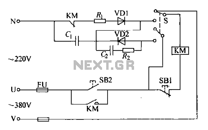
AC contactor silent operation of the circuit
The AC contactor operates silently, demonstrating significant energy-saving effects, low noise, and a reduced operating temperature, which contributes to an extended lifespan. It is widely utilized in the production industry. When the SB2 button is pressed, the N-terminal receives a...
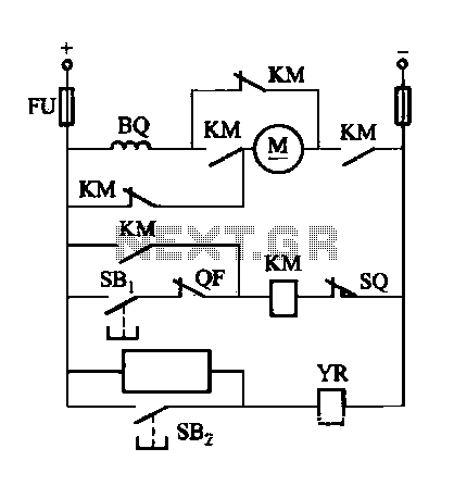
DW16M-630 type DC excitation switch control circuit
The DW16M-630 type excitation switch operates with both DC and AC power. The circuit for DC operation is illustrated in Figure 7-60, while the circuit for AC operation is shown in Figure 7-61. The BQ single-phase series motor M features...
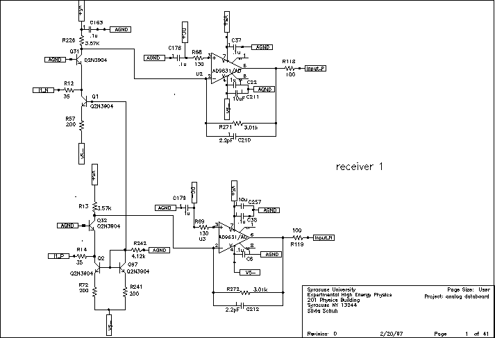
Chip carrier test
VA-RICH Power consumption: -2V current draws 34 mA, +2V current draws 5 mA. Total power consumption is 68 mW. Spark protection: Spark protection works, but the spark current burns the trace from pad to input transistor, which makes the channel...
Chip carrier test
VA-RICH Power consumption: -2V current draws 34 mA, +2V current draws 5 mA. Total power consumption is 68 mW. Spark protection: Spark protection works, but the spark current burns the trace from pad to input transistor, which makes the channel...
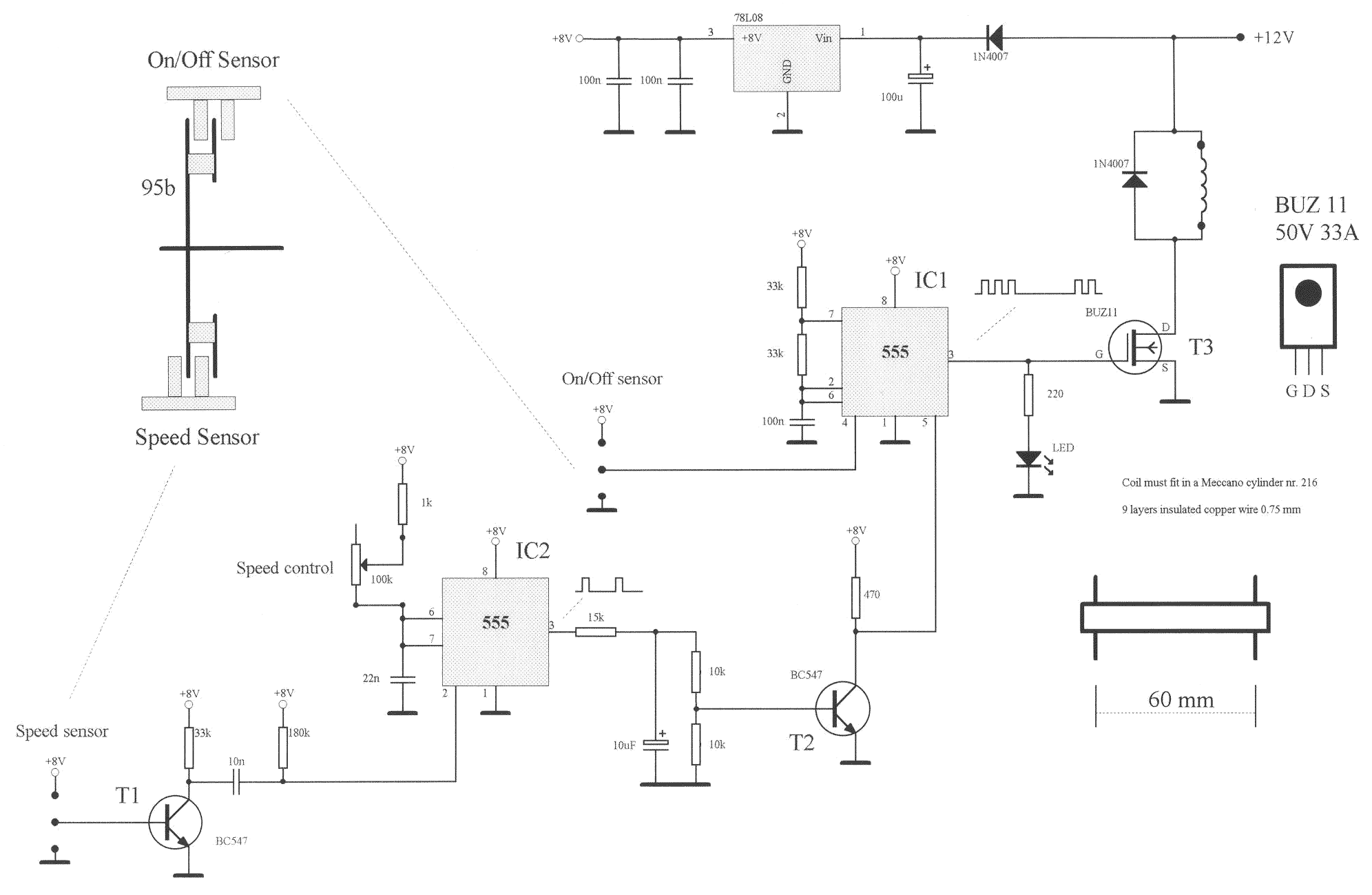
Horizontal Electric Engine
A model has been constructed based on the principles of a horizontal steam engine, where the steam cylinder is substituted with an electromagnet featuring a moving core. The construction specifics are less significant, as the accompanying photos provide all necessary...
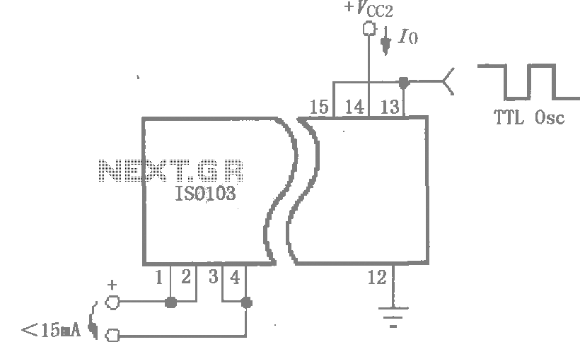
Reducing the power consumption of the circuit diagram ISO103
This circuit is designed to reduce power consumption in an ISO103 application. It operates with a Vcc1 current of less than 15mA for multi-channel synchronous applications. An oscillator, as illustrated in the figure, can be utilized to generate a TTL...
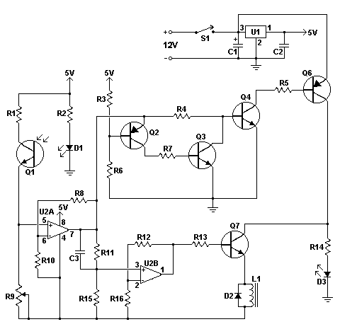
electromagnetic levitator circuit
This circuit creates an impressive display of magnetism by suspending a small metal object in mid-air. Utilizing an electromagnet, a photo sensor, and a closed-loop control system, lightweight metal objects can be levitated just beneath the magnet, enclosed in a...
DW16M-630 type DC excitation switch control circuit
The DW16M-630 type excitation switch operates with both DC and AC power. The circuit for DC operation is illustrated in Figure 7-60, while the circuit for AC operation is shown in Figure 7-61. The BQ single-phase series motor M features...