


L4960 by a monolithic switching power supply
#L4960
#switching power supply
#voltage regulator
#step-down transformer
#bridge rectifier
#filter
#DC voltage
#monolithic
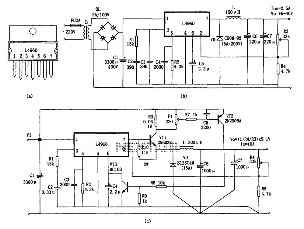
Description: The circuit shown in the figure consists of an L4960 switching power supply that operates with an input voltage range of +5 to +40V. The AC 220V voltage is transformed down through a step-down transformer, followed by a bridge rectifier and a filter to produce the DC voltage (Vi). The L4960 regulates the output voltage through its internal soft-start mechanism, which gradually increases the output voltage. The voltage at R3 and R4 is sampled and compared by the internal error amplifier against a 5.1V reference voltage, generating an error voltage. This error voltage is then used to control the pulse width modulation (PWM) comparator, which adjusts the power output stage. The amplification and step-down output circuit, consisting of components L, VD, C6, and C7, ensures that the output voltage (Vo) remains stable. The L4960's pin 7 outputs a power pulse modulation signal, which, when the internal switching power MOSFET is active, allows energy to be stored in the inductors L and capacitors C6 and C7, while the freewheeling diode VD is inactive. Conversely, when the MOSFET is off, VD conducts, allowing the stored energy in L to discharge through the load, thus maintaining a constant output voltage Vo. Additionally, a current spreading circuit is implemented using an external power transistor to extend the output current capability to 10A. Over-current protection is provided by components VT2, VT3, and resistors R5, R6, R7, R8, and R9. If the output current exceeds 10A, the protection circuit clamps the L4960's pin to 0V, disabling the PWM comparator and terminating the output current.
The L4960 is a highly integrated switching regulator that is designed to provide a stable output voltage from a varying input voltage. The operation begins with the AC mains voltage being stepped down by a transformer to a lower AC voltage, which is then rectified by a bridge rectifier into DC voltage. This DC voltage is filtered to smooth out any ripples, providing a steady input voltage (Vi) for the L4960.
The internal soft-start feature of the L4960 is crucial for preventing inrush current that can damage components during the initial power-up phase. By gradually increasing the output voltage, the circuit ensures that the connected load is not subjected to sudden surges of current. The feedback mechanism involving resistors R3 and R4 plays a vital role in maintaining output voltage regulation. The sampled voltage is compared to a precise reference voltage of 5.1V, and any deviation results in an error voltage that drives the PWM comparator.
The PWM comparator modulates the width of the output pulses sent to the power output stage, which consists of a switching power MOSFET. This modulation effectively controls the amount of energy transferred to the output load. The energy storage components, including the inductor L and capacitors C6 and C7, work together to smooth out the output voltage, ensuring that it remains constant despite variations in load current.
The current spreading circuit enhances the L4960's output capability, allowing it to handle higher current loads up to 10A. This is achieved through the addition of an external power transistor that shares the load current, preventing overheating and ensuring reliable operation. The over-current protection circuit is a critical safety feature that prevents damage to the L4960 and connected components. When the output current exceeds the threshold of 10A, the circuit activates, clamping the voltage at the L4960's pin to 0V, effectively disabling the PWM control and stopping the output current flow to protect the system from damage.
In summary, the L4960 switching power supply circuit is designed for efficiency and reliability, with built-in features for voltage regulation, current sharing, and over-current protection, making it suitable for a variety of applications requiring stable power delivery. As shown in FIG constituted by L4960 + 5 ~ + 40V switching power supply circuit. AC 220V voltage through the step-down transformer, bridge rectifier and filter DC voltage Vi, i nput L4960 O feet, under the action of L4960 internal soft-start circuit, the output voltage gradually increased. When the entire internal circuit is functioning normally, the output voltage in R3, R4 after sampling returned feet, internal error amplifier is compared with a 5.1V reference voltage to obtain the error voltage, then the magnitude of the error voltage to control the PWM comparator the pulse width, the power output stage after amplification and step-down output circuits (constituted by L, VD, C6 and C7), the output voltage Vo remains constant.
L4960 7 feet get is power pulse modulation signal, which is high (L4960 internal switching power MOSFET) when, in addition to the load, as well as part of the energy stored in L and C6, C7, in which case freewheeling VD deadline. When power low-power pulse signal (switching power MOSFET is off) when, VD conduction, stored in L on through the loop formed by VD configured to load discharge, thereby maintaining the output voltage Vo constant.
Figure (c) shows a current spreading circuit L4960. This circuit uses an external power transistor approach. The output current is extended to 10A. And over-current protection circuit is provided by the VT2, VT3 and R5, R6, R7, R8, R9 other components, when the output current is greater than 10A, the protection circuit, the potential of the L4960 foot clamp to 0V, closed PWM comparator terminates the output current.
The L4960 is a highly integrated switching regulator that is designed to provide a stable output voltage from a varying input voltage. The operation begins with the AC mains voltage being stepped down by a transformer to a lower AC voltage, which is then rectified by a bridge rectifier into DC voltage. This DC voltage is filtered to smooth out any ripples, providing a steady input voltage (Vi) for the L4960.
The internal soft-start feature of the L4960 is crucial for preventing inrush current that can damage components during the initial power-up phase. By gradually increasing the output voltage, the circuit ensures that the connected load is not subjected to sudden surges of current. The feedback mechanism involving resistors R3 and R4 plays a vital role in maintaining output voltage regulation. The sampled voltage is compared to a precise reference voltage of 5.1V, and any deviation results in an error voltage that drives the PWM comparator.
The PWM comparator modulates the width of the output pulses sent to the power output stage, which consists of a switching power MOSFET. This modulation effectively controls the amount of energy transferred to the output load. The energy storage components, including the inductor L and capacitors C6 and C7, work together to smooth out the output voltage, ensuring that it remains constant despite variations in load current.
The current spreading circuit enhances the L4960's output capability, allowing it to handle higher current loads up to 10A. This is achieved through the addition of an external power transistor that shares the load current, preventing overheating and ensuring reliable operation. The over-current protection circuit is a critical safety feature that prevents damage to the L4960 and connected components. When the output current exceeds the threshold of 10A, the circuit activates, clamping the voltage at the L4960's pin to 0V, effectively disabling the PWM control and stopping the output current flow to protect the system from damage.
In summary, the L4960 switching power supply circuit is designed for efficiency and reliability, with built-in features for voltage regulation, current sharing, and over-current protection, making it suitable for a variety of applications requiring stable power delivery. As shown in FIG constituted by L4960 + 5 ~ + 40V switching power supply circuit. AC 220V voltage through the step-down transformer, bridge rectifier and filter DC voltage Vi, i nput L4960 O feet, under the action of L4960 internal soft-start circuit, the output voltage gradually increased. When the entire internal circuit is functioning normally, the output voltage in R3, R4 after sampling returned feet, internal error amplifier is compared with a 5.1V reference voltage to obtain the error voltage, then the magnitude of the error voltage to control the PWM comparator the pulse width, the power output stage after amplification and step-down output circuits (constituted by L, VD, C6 and C7), the output voltage Vo remains constant.
L4960 7 feet get is power pulse modulation signal, which is high (L4960 internal switching power MOSFET) when, in addition to the load, as well as part of the energy stored in L and C6, C7, in which case freewheeling VD deadline. When power low-power pulse signal (switching power MOSFET is off) when, VD conduction, stored in L on through the loop formed by VD configured to load discharge, thereby maintaining the output voltage Vo constant.
Figure (c) shows a current spreading circuit L4960. This circuit uses an external power transistor approach. The output current is extended to 10A. And over-current protection circuit is provided by the VT2, VT3 and R5, R6, R7, R8, R9 other components, when the output current is greater than 10A, the protection circuit, the potential of the L4960 foot clamp to 0V, closed PWM comparator terminates the output current.
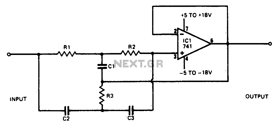
Rejection filter
This narrowband filter utilizing the 741 operational amplifier can achieve a rejection level of up to 60 dB. By employing resistors with a value of 100 K ohms and capacitors of 320 pF, the circuit effectively rejects frequencies at 50...
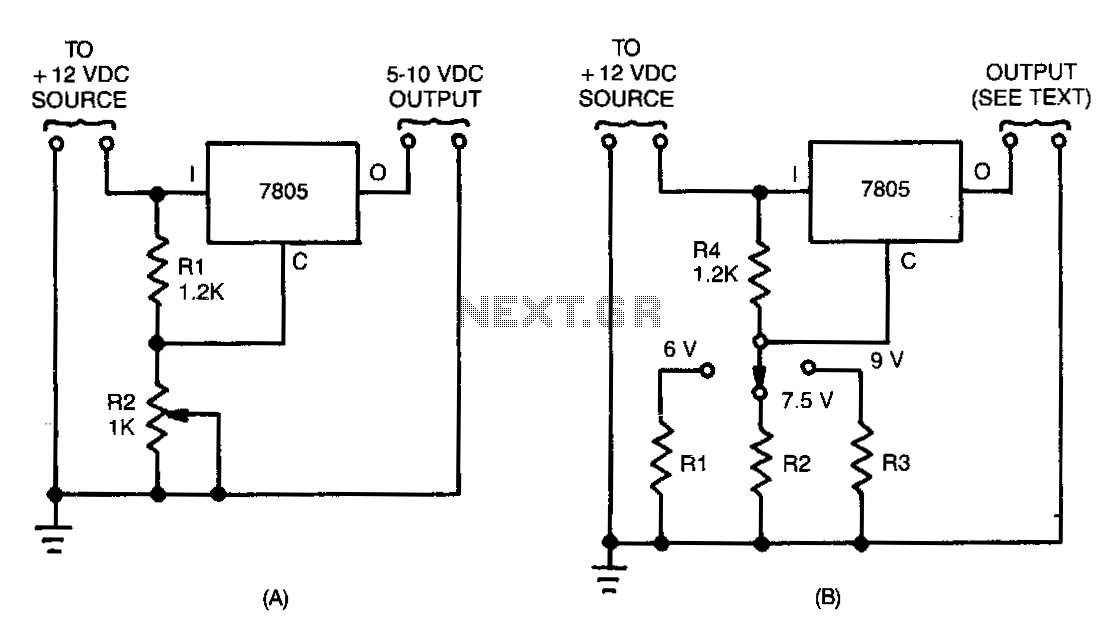
12-16V-converter
Many devices operate from a car's 12-V electrical system. Some require 12 V, while others need a lower voltage. An automobile battery's output can vary from 12 to 13.8 V under normal circumstances. The load requirements of the device may...
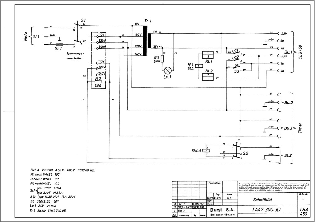
Durst power supplies EST 301 and EST 450
The regulator board of the ES301 has been inspected, revealing that the PCB contacts of the current sensing resistors R42 and R43 are severely burned. There is a nearby group of resistors that also need to be replaced, but their...
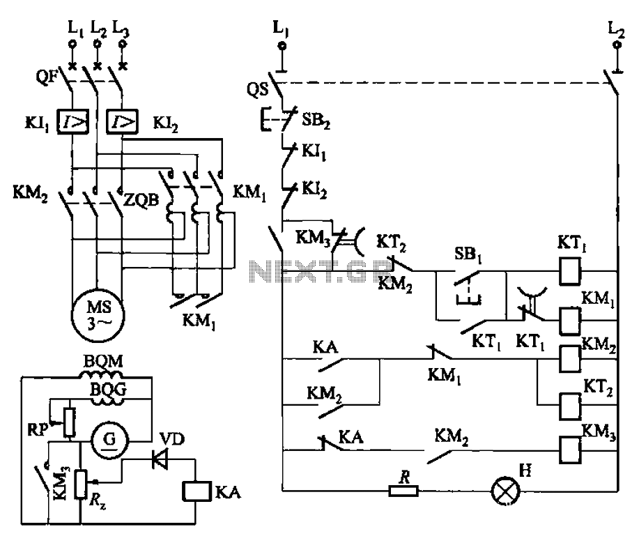
Step-down autotransformer rotor excitation frequency starting circuit
The circuit depicted in Figure 3-187 illustrates the operation of an auto step-down transformer (ZQB). Upon activation, the ZQB transformer initiates a sequence that allows the motor to gradually increase its speed. After a predetermined delay, the ZQB ceases operation,...
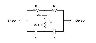
Twin-T RC Notch Filter
The two T-notch filter can be utilized to block unwanted frequencies or, when incorporated into an operational amplifier, function as a bandpass filter. The notch frequency occurs when the capacitive reactance equals the resistance (Xc = R), and if these...
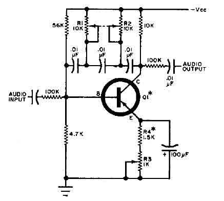
Q-multiplier filter circuit
This circuit is designed for selective tuning adjustments between two closely spaced audio tones. The frequency is determined by the values of the capacitors and resistors in the feedback circuit connecting the collector and base of transistor Q1. With the...
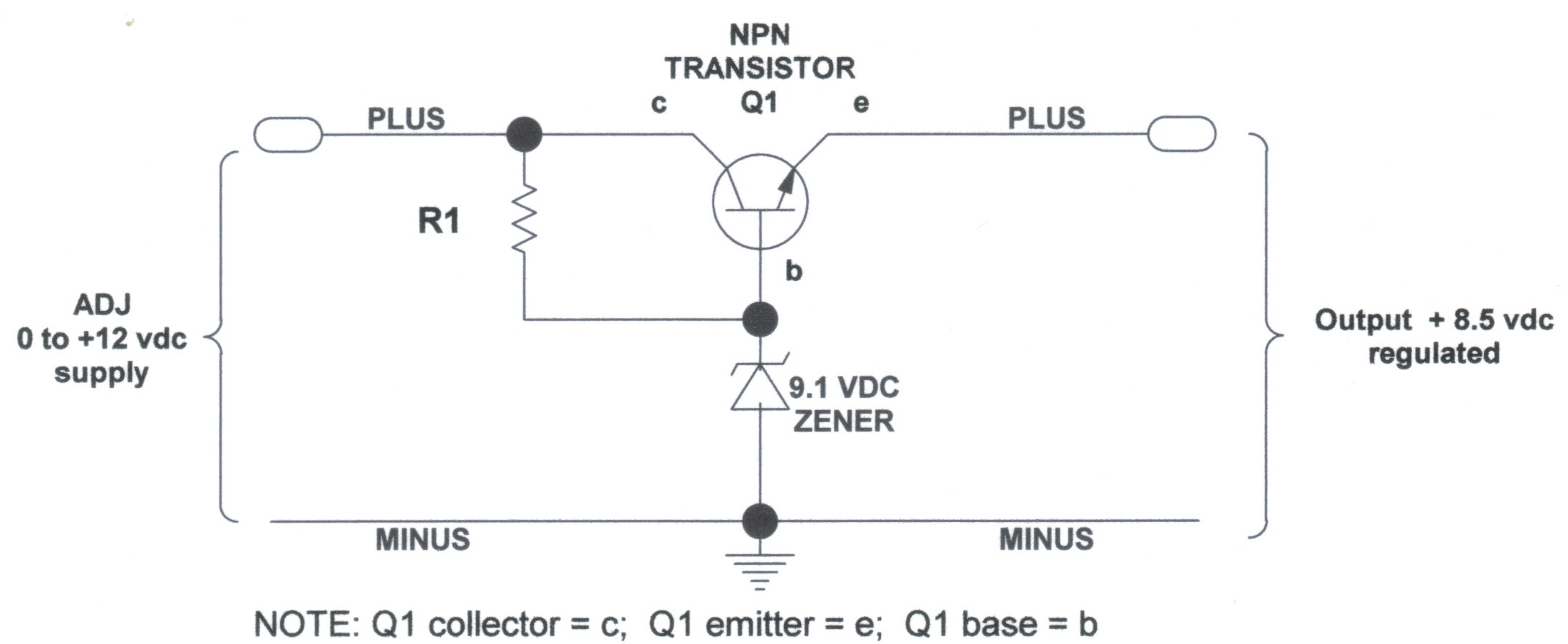
voltage regulators
DC Voltage Regulator (NPN & Zener Regulator) There are instances where it is handy to have a regulated DC voltage power supply for use on your model.
A DC voltage regulator is an essential component in electronic circuits that provides a...

LM567CM Integrated Circuits
LM5576MHX absolute maximum ratings: (1) VIN to GND: 76V; (2) BST to GND: 90V; (3) PRE to GND: 76V; (4) SW to GND (Steady State): -1.5V; (5) BST to VCC: 76V; (6) SD, VCC to GND: 14V; (7) BST to...
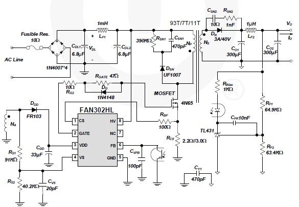
FAN302HL 5 volt switching power supply circuit design electronic project
A simple 5-volt switching power supply electronic circuit project can be designed using the FAN302HL, a highly integrated PWM controller integrated circuit. This IC provides several features that enhance the performance of general flyback converters. The constant-current control of the...