


Low Cost Capacitive Touch Switch II circuit schematic with explanation
#capacitive touch
#touch switch
#low cost
#switching
#sensor
#load control
#electronics
#DIY
#circuit design
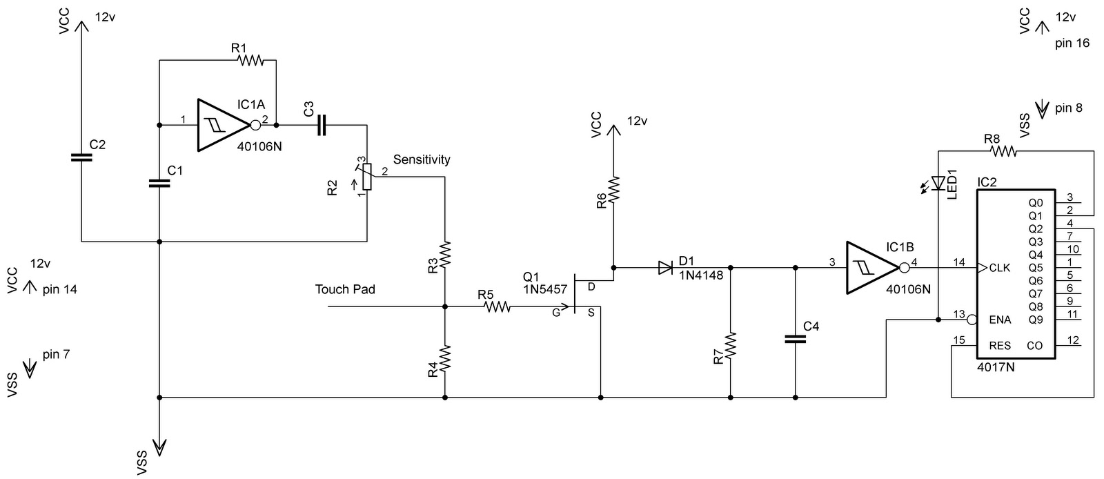
Description: In the previous post regarding a capacitive touch switch, the output was activated only while the touch was maintained. This means that the circuit would drive the load only during the touch, and once the touch was removed, it would cease to drive the load. Although the touch switch circuit can be utilized in various applications, it did not meet the specific requirements. By making slight modifications to the circuit, a touch switch was designed to function like a conventional switch, allowing it to be turned on and off with a touch. This design incorporates the CD4017 decade counter. The output from a CD4016 drives this counter, with the load connected to pin 2 of the counter and the reset connected to pin 4. When the touch plate (a wire in this case) is activated, a pulse is sent to the counter, incrementing its output. As the load is connected to Q1 of the counter, the output becomes high, enabling the load to be driven. To turn off the load, the touch plate must be activated again; this causes the counter to increment once more, reset itself, and set Q0 high. Since the load is not connected to this pin, it will turn off.
The touch switch circuit designed with the CD4017 decade counter provides a versatile solution for applications requiring a touch-activated on/off mechanism. The CD4017 is a popular decade counter IC that counts from 0 to 10 and provides ten outputs (Q0 to Q9). In this configuration, the touch plate serves as the input trigger, sending a pulse to the clock input of the CD4017 every time it is touched.
When the circuit is powered, the CD4017 begins at an initial state of Q0 being high and all other outputs low. The output connected to Q1 is used to drive the load. Upon the first touch of the plate, the CD4017 increments to Q1, turning on the load. A second touch increments the counter again, resetting the output to Q0, which turns off the load. This toggle function effectively allows the user to control the load with a single touch plate, simplifying the user interface.
Additional components may be incorporated into the circuit for enhanced functionality, such as debounce circuitry to prevent false triggering due to noise or unintended touches. A capacitor can be placed in parallel with the touch plate to filter out high-frequency noise, ensuring that only deliberate touches are registered.
Furthermore, the use of a pull-down resistor at the input can help stabilize the input signal when the touch plate is not activated, preventing floating states that might lead to erratic behavior. The circuit can be powered by a standard DC voltage supply, compatible with the operating range of the CD4017, typically between 3V and 15V.
This design not only meets the requirement for a touch-activated switch but also offers a reliable and efficient method for controlling electrical loads in various applications, including lighting systems, appliances, and automated devices.In my previous post of capacitive touch switch, it gives the o/p as long as you touch it. Means it was only drive the load when you touch it, and when you remove your hand/finger then it was not able to drive the load. Tough that touch switch circuit can be used in various apps but does not meet my requirements. So by changing the circuit a little bit i am able to design a touch switch that behave like a normal switch i. e touch to on and touch to off. For this i used CD4017 decade counter. Output of 40106 drives this counter and load is connected to the pin2 of the counter, and reset is to pin4. When you touch the touch plate (wire in my case) a pulse is provided to the counter and it increments its o/p.
So as the load is connected to the Q1 of counter, the o/p is high to drive the load. Similarly if you want to switch off the load and again touch the plate; counter will increment again and reset itself and make Q0 high. As your load is not connected to this pin it will go off. That is all!.
The touch switch circuit designed with the CD4017 decade counter provides a versatile solution for applications requiring a touch-activated on/off mechanism. The CD4017 is a popular decade counter IC that counts from 0 to 10 and provides ten outputs (Q0 to Q9). In this configuration, the touch plate serves as the input trigger, sending a pulse to the clock input of the CD4017 every time it is touched.
When the circuit is powered, the CD4017 begins at an initial state of Q0 being high and all other outputs low. The output connected to Q1 is used to drive the load. Upon the first touch of the plate, the CD4017 increments to Q1, turning on the load. A second touch increments the counter again, resetting the output to Q0, which turns off the load. This toggle function effectively allows the user to control the load with a single touch plate, simplifying the user interface.
Additional components may be incorporated into the circuit for enhanced functionality, such as debounce circuitry to prevent false triggering due to noise or unintended touches. A capacitor can be placed in parallel with the touch plate to filter out high-frequency noise, ensuring that only deliberate touches are registered.
Furthermore, the use of a pull-down resistor at the input can help stabilize the input signal when the touch plate is not activated, preventing floating states that might lead to erratic behavior. The circuit can be powered by a standard DC voltage supply, compatible with the operating range of the CD4017, typically between 3V and 15V.
This design not only meets the requirement for a touch-activated switch but also offers a reliable and efficient method for controlling electrical loads in various applications, including lighting systems, appliances, and automated devices.In my previous post of capacitive touch switch, it gives the o/p as long as you touch it. Means it was only drive the load when you touch it, and when you remove your hand/finger then it was not able to drive the load. Tough that touch switch circuit can be used in various apps but does not meet my requirements. So by changing the circuit a little bit i am able to design a touch switch that behave like a normal switch i. e touch to on and touch to off. For this i used CD4017 decade counter. Output of 40106 drives this counter and load is connected to the pin2 of the counter, and reset is to pin4. When you touch the touch plate (wire in my case) a pulse is provided to the counter and it increments its o/p.
So as the load is connected to the Q1 of counter, the o/p is high to drive the load. Similarly if you want to switch off the load and again touch the plate; counter will increment again and reset itself and make Q0 high. As your load is not connected to this pin it will go off. That is all!.
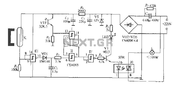
Gate automatic lamp circuit
The circuit utilizes multiple integrated circuits to form an automatic lighting device that is activated by door and window sensors. It includes CD4093 digital integrated circuits, a relay, and a power supply circuit. The system typically remains closed when a...
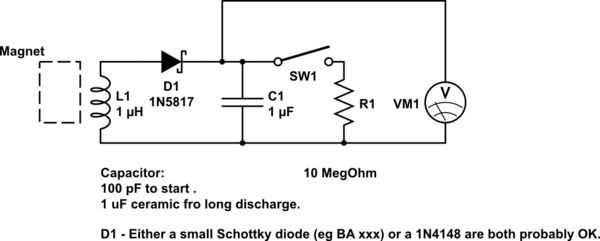
DIY kinetic energy harvester
A DIY kinetic energy harvester utilizing the electromagnetic method to generate electricity. The materials that will be used are currently known.
The project involves creating a kinetic energy harvester that converts mechanical energy from motion into electrical energy through electromagnetic induction....
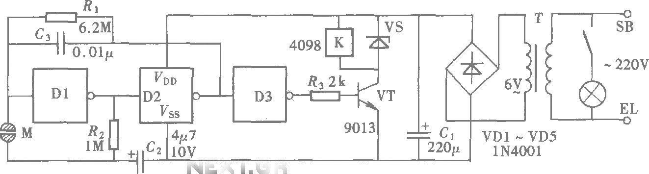
Door touch switch circuit (CD4069) schematic
A CMOS gate exhibits high input impedance, which allows it to respond to changes in input levels due to human contact, thereby triggering the toggling of gates. The circuit utilizes this characteristic to create a touch lamp switch. The circuit,...
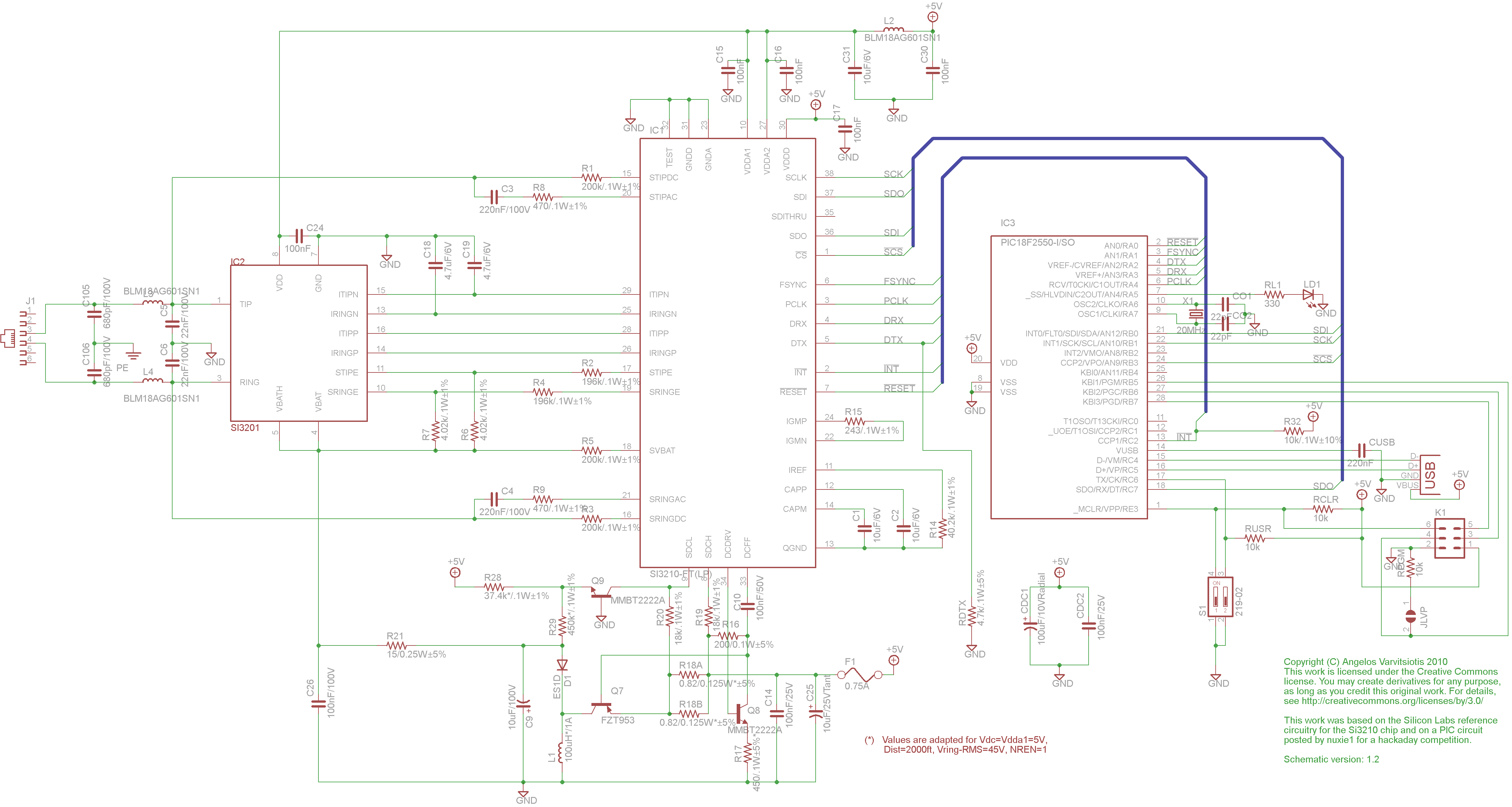
dyi setup and debugging guide
This page discusses the differences between assembled Open USB FXS dongle boards and DIY boards. While the assembled boards are fully tested and quality control approved, DIY boards may encounter various issues during assembly. Fortunately, most of these issues can...
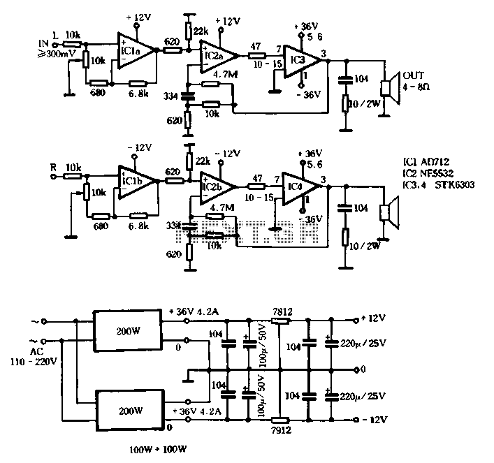
Switching power supply circuit with STK6303
The T amplifier circuit schematic section is illustrated in Figure 3-51. It utilizes the Japan Sanyo STK6303 Pina, which is a high-power thick film integrated circuit. The maximum power supply voltage is 36V, and the output current can reach approximately...
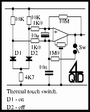
Touch Switches Collection
Touch operated switches are an attractive project for DIY electronics but they are not so common in commercial products. The reason for this is that, although there are many different ways of implementing a touch switch (leakage, hum pickup, capacitance,...
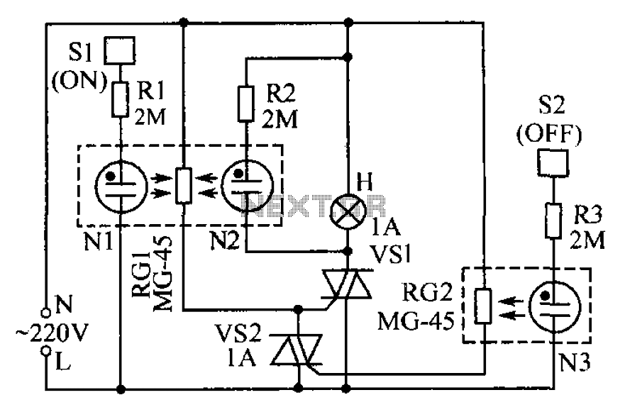
Lamp touch switch circuit diagram
The circuit operates based on the principle that neon tubes N1, N2, and the photosensitive resistor RG1 form an optocoupler. When a finger touches the metal sheet S1, N1 lights up, causing RG1's resistance to decrease. This reduction allows the...

Low Cost Universal Battery Charger Schematic
This is a simple and low-cost NiCd and NiMH battery charger. The schematic diagram indicates that the charging current (I) should be set to 1/10 of the battery's rated capacity. For instance, if the battery has a rated capacity of...
Glue stck torch
This project, developed around 2005, involves constructing a torch using a glue stick, which conveniently accommodates an AA battery within its plastic casing. To create a functional battery holder, contacts for both the positive and negative connections are necessary. The...