


Phone Line Simulator with PIC16F819
#PIC16F819
#phone line
#simulator
#48V DC
#100V AC
#off-hook
#ring signal
#telecommunication
#voltage generation
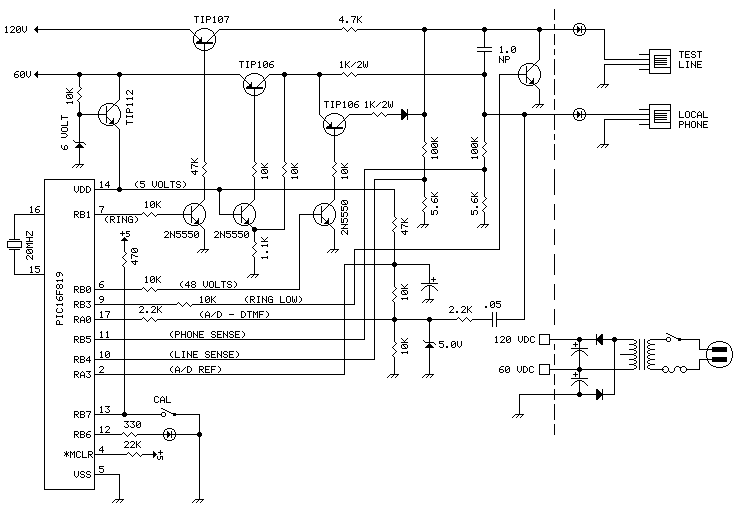
Description: Creating projects that connect to the phone line can be a real chore without some device like this. It generates the 48 volts DC for the on-hook condition, the 100 volts AC for the ring signal, and the 20 milliamperes DC for the off-hook condition. To use the device, a phone is connected to the left jack. When it is picked up (off-hook), a ring signal is generated at the right jack. More: When the device on that jack goes off-hook, the ring is terminated, 20 ma is provided through 600 ohms, and the 2 lines are connected for audio. When the phone is hung up, a 250 ms line break is created on the other jack to indicate the end of the phone connection. This allows testing of incoming phone devices only (i.e. answering devices). Here are the Source, Object, and Schematic files.
The described device is a telephone line simulation circuit that facilitates the testing of incoming telephone devices, such as answering machines or caller ID systems. It operates by generating the necessary voltages and currents to replicate the conditions of a standard telephone line.
In the on-hook condition, the device provides 48 volts DC, which is the typical voltage present on an idle phone line. This voltage is essential for maintaining the phone in a ready state without drawing significant current. When the telephone is picked up (off-hook), the device switches to provide a 20 mA DC current through a 600-ohm resistor, which simulates the active state of a telephone line.
The circuit also generates a 100 volts AC ringing signal, which is used to alert the connected device of an incoming call. This signal is present at the right jack and is terminated when the connected device goes off-hook. The transition from on-hook to off-hook state is critical for the proper functioning of the testing device, as it allows the device to simulate real-world telephone line behavior.
Furthermore, when the phone is hung up, the circuit introduces a 250 ms line break at the opposite jack. This brief interruption in the line simulates the disconnection process, which is necessary for the testing of devices that need to recognize the end of a call.
The design of this circuit is particularly useful for engineers and developers working on telecommunications equipment, as it allows for thorough testing without the need for an actual phone line. The source, object, and schematic files mentioned would typically include the necessary design and layout information for constructing the circuit on a breadboard or PCB, ensuring that all components are correctly configured for optimal performance.Creating projects that connect to the phone line can be a real chore without some device like this. It generates the 48 volts DC for the on-hook condition, the 100 volts AC for the ring signal, and the 20 milliamperes DC for the off-hook condition. To use the device, a phone is connected to the left jack. When it is picked up (off-hook), a ring signal is generated at the right jack. When the device on that jack goes off-hook, the ring is terminated, 20 ma is provided thru 600 ohms, and the 2 lines are connected for audio. When the phone is hung up, a 250 ms line break is created on the other jack to indicate the end of the phone connection.
This allows testing of incomming phone devices only (i.e. answering devices). Here are the Source, Object, and Schmatic files.
The described device is a telephone line simulation circuit that facilitates the testing of incoming telephone devices, such as answering machines or caller ID systems. It operates by generating the necessary voltages and currents to replicate the conditions of a standard telephone line.
In the on-hook condition, the device provides 48 volts DC, which is the typical voltage present on an idle phone line. This voltage is essential for maintaining the phone in a ready state without drawing significant current. When the telephone is picked up (off-hook), the device switches to provide a 20 mA DC current through a 600-ohm resistor, which simulates the active state of a telephone line.
The circuit also generates a 100 volts AC ringing signal, which is used to alert the connected device of an incoming call. This signal is present at the right jack and is terminated when the connected device goes off-hook. The transition from on-hook to off-hook state is critical for the proper functioning of the testing device, as it allows the device to simulate real-world telephone line behavior.
Furthermore, when the phone is hung up, the circuit introduces a 250 ms line break at the opposite jack. This brief interruption in the line simulates the disconnection process, which is necessary for the testing of devices that need to recognize the end of a call.
The design of this circuit is particularly useful for engineers and developers working on telecommunications equipment, as it allows for thorough testing without the need for an actual phone line. The source, object, and schematic files mentioned would typically include the necessary design and layout information for constructing the circuit on a breadboard or PCB, ensuring that all components are correctly configured for optimal performance.Creating projects that connect to the phone line can be a real chore without some device like this. It generates the 48 volts DC for the on-hook condition, the 100 volts AC for the ring signal, and the 20 milliamperes DC for the off-hook condition. To use the device, a phone is connected to the left jack. When it is picked up (off-hook), a ring signal is generated at the right jack. When the device on that jack goes off-hook, the ring is terminated, 20 ma is provided thru 600 ohms, and the 2 lines are connected for audio. When the phone is hung up, a 250 ms line break is created on the other jack to indicate the end of the phone connection.
This allows testing of incomming phone devices only (i.e. answering devices). Here are the Source, Object, and Schmatic files.
phone busy circuit
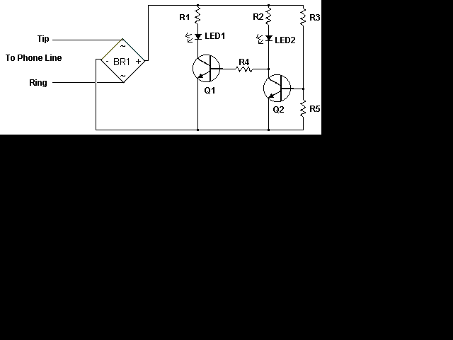
This circuit addresses the issue of phone line interruptions caused by simultaneous use of a modem or fax machine when another phone is picked up. It indicates the status of the phone line by illuminating a red LED when the...
Phone line in use drives Relay
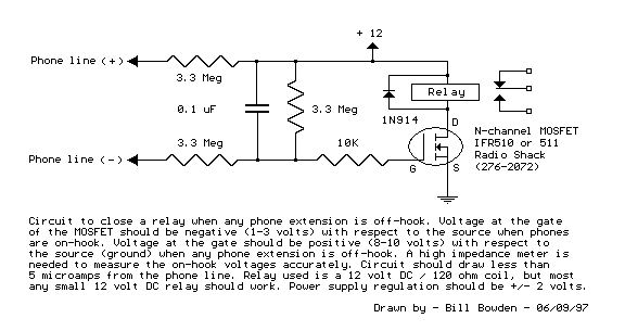
Circuit to close a relay when any phone extension is off-hook. Voltage at the gate of the MOSFET should be negative (1-3 volts) with respect to the source when phones are on-hook. Voltage at the gate should be positive (8-13...
Circuit Detects Phone-Line Breaks
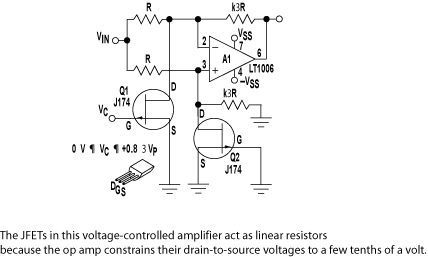
Alarm system designs often require circuitry that can detect whether a phone line is active or broken. The primary challenge in this design is to draw less than 5 µA from the phone line, which operates within a voltage range...
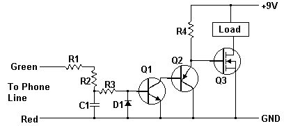
Cut Phone Line Detector
A while ago I got an email asking for the schematic of a circuit to detect cut phone lines. It didn’t take me long to find this circuit in Electronics Now. When the circuit detects that a phone line has...
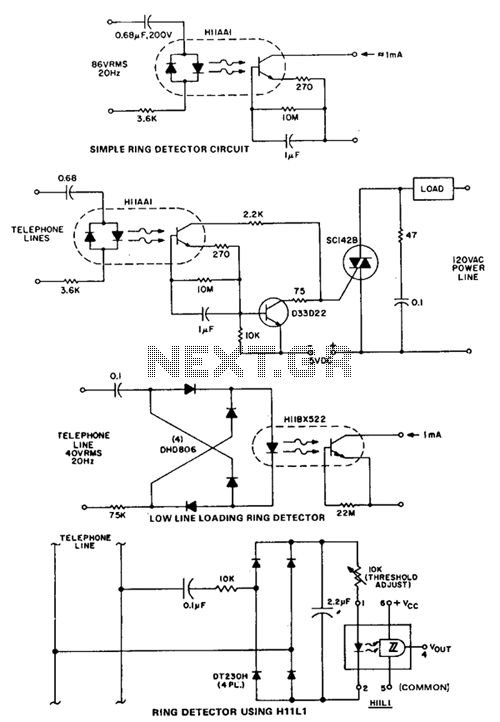
Ring-detector
This circuit detects the 20 Hz, 86-V rms ring signal on telephone lines and initiates action in an electrically isolated circuit. Typical applications include automatic answering equipment, interconnect/interface systems, and key systems. The illustrated circuits are basic designs intended to...
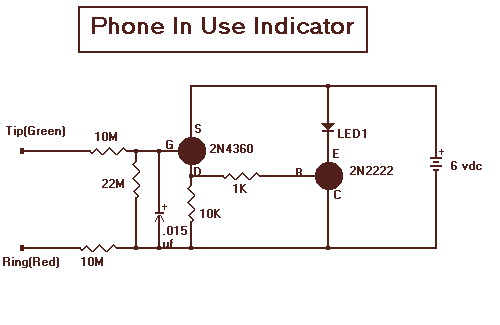
Phone Line In use LED with 2N2222
With this circuit mounted in or near every phone in the house, it will allow users to know if the phone is being used and not to pick up the phone. When a phone is taken off hook, the voltage...
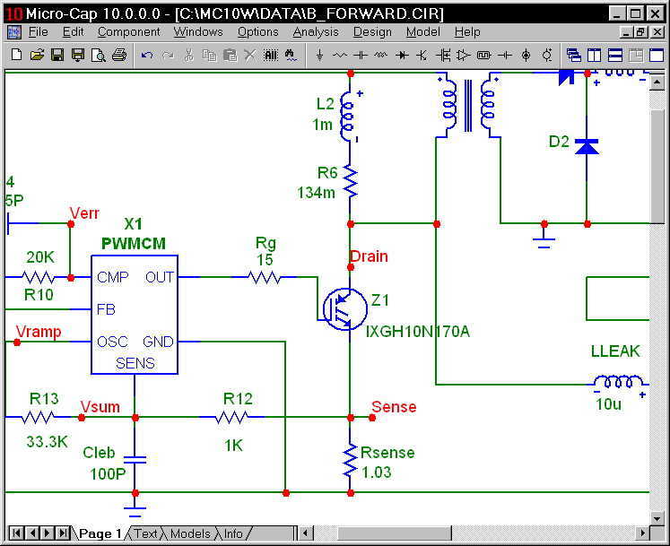
Micro-Cap 9
Micro-Cap 9 is an integrated schematic editor and mixed analog/digital simulator that provides an interactive sketch and simulate environment for electronics engineers. Since its original release in 1982, Micro-Cap has been steadily expanded and improved. Micro-Cap 9, the eighth generation,...
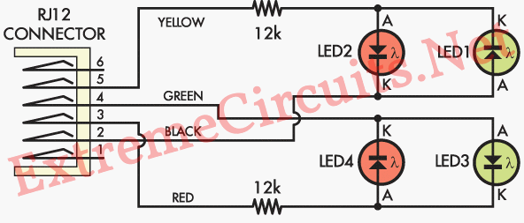
Phone Line Polarity Checker
If there is a suspicion that the broadband speed (DSL) is slower than expected, it may be due to incorrect polarity in the phone wall socket. A simple and inexpensive device can be built to determine if the wiring needs...
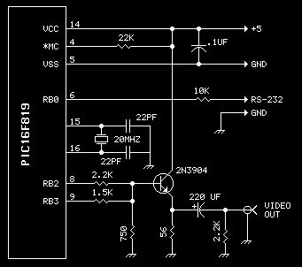
Video title generator
Want to add video to your next project? This device uses a PIC16F819 and not much else. Getting 20 characters to a line is possible by using the SPI port to generate video. Neat trick, eh? The character set is...