


Telephone hold button
#telephone
#hold button
#SCR
#silicon control rectifier
#voltage drop
#on-hook
#off-hook
#circuit
#communication
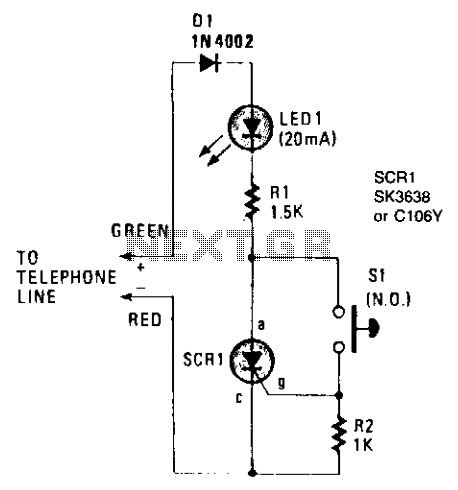
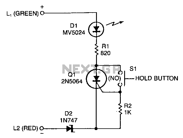
Description: The on-hook (no load) voltage across the red-green wires will be 48 V or slightly less when all telephones are on-hook (disconnected). When any telephone goes off-hook, the load current flowing in the telephone causes the voltage to fall below 5 volts DC. Although the telephone hold is connected across the red-green wires, silicon control rectifier SCR1 is open; thus, there is no current path across the telephone line. To hold the call, the normally-open switch S1 must be depressed while hanging up the telephone (keeping S1 depressed). When the phone goes on-hook, the red-green voltage jumps to 48 volts DC. Since switch S1 is closed, a positive voltage is applied to SCR1's gate, causing SCR1 to conduct and completing the circuit across the telephone line through D1, LED1, R1, and SCR1. The current flowing through these components also causes the LED to light up, indicating that the telephone line is being held. The effective load across the red-green wires is the 1500-ohm value of R1, which is sufficient to seize the line while limiting the current through the LED to a safe value. When the telephone, or an extension, is placed off-hook again, the red-green voltage falls to 5 volts or less. However, diode D1 has a normal voltage drop—referred to as the breakover voltage—of 0.7 volts, and the LED has a forward drop of 2.0 volts. Excluding the voltage drop across R1, a maximum of 2.3 volts is available for SCR1, which is too low to maintain conduction; thus, SCR1 automatically opens the hold circuit when any telephone goes off-hook.
The circuit described involves a telephone line hold mechanism utilizing a silicon control rectifier (SCR) and several passive components. The system operates under two primary states: on-hook and off-hook. In the on-hook state, the voltage across the red-green wires remains at approximately 48 volts DC, indicating that no telephone is actively using the line. When a telephone goes off-hook, it draws current, which reduces the voltage to below 5 volts DC, indicating active use of the line.
The SCR, designated as SCR1, plays a crucial role in maintaining the hold state of the call. When a user hangs up the phone while keeping switch S1 depressed, the voltage across SCR1's gate becomes sufficient to trigger conduction, allowing current to flow through the circuit. This current path includes diode D1, LED1, and resistor R1, with R1 providing a load of 1500 ohms. This resistance is carefully selected to ensure that the line can be seized without exceeding the safe operating current for LED1, which visually indicates that the line is held.
Once the telephone is placed off-hook again, the voltage across the red-green wires drops substantially. The voltage drop across D1 (0.7 volts) and LED1 (2.0 volts) leaves insufficient voltage for SCR1 to remain conductive, as only 2.3 volts is available. Consequently, SCR1 turns off, effectively releasing the hold on the line. This design ensures that the system can seamlessly transition between holding a call and releasing it based on the state of the telephone, thereby maintaining proper line management and user control.The on-hook (no load) voltage across the red-green wires will be 48 V or slightly less when all telephones are on-hook (disconnected). When any telephone goes off-hook the load current flowing in the telephone causes the voltage to fall below 5 volts dc.
Although the telephone hold is connected across the red-green wires, silicon control rectifier SCRl is open; so there is no current path across the telephone line. To hold the call, depress normally-open switch SI and hang up the telephone (still depressing SI). When the phone goes on-hook the red-green voltage jumps to 48 volts dc. Since switch SI is closed, a positive voltage is applied to SCRl's gate, which causes SCRl to conduct, thereby completing the circuit across the telephone line through Dl, LED1, Rl, and SCRl.
The current that flows through those components also causes the LED to light up—indicating that the telephone line is being held. The effective load across the red-green wires is the 1500 ohm value of Rl, which is sufficient to seize the line while limiting the current through the LED to a safe value.
When the telephone, or an extension, is once again placed off-hook the red-green voltage falls to 5 volts or less. But diode Dl has a normal voltage drop—called the breakover voltage—of 0.7 volts, and the LED has a forward drop of 2.0 volts.
Excluding the voltage drop across Rl there is a maximum of 2.3 volts available for SCRl, which is too low to maintain conduction; so SCRl automatically opens the hold circuit when any telephone goes off-hook.
The circuit described involves a telephone line hold mechanism utilizing a silicon control rectifier (SCR) and several passive components. The system operates under two primary states: on-hook and off-hook. In the on-hook state, the voltage across the red-green wires remains at approximately 48 volts DC, indicating that no telephone is actively using the line. When a telephone goes off-hook, it draws current, which reduces the voltage to below 5 volts DC, indicating active use of the line.
The SCR, designated as SCR1, plays a crucial role in maintaining the hold state of the call. When a user hangs up the phone while keeping switch S1 depressed, the voltage across SCR1's gate becomes sufficient to trigger conduction, allowing current to flow through the circuit. This current path includes diode D1, LED1, and resistor R1, with R1 providing a load of 1500 ohms. This resistance is carefully selected to ensure that the line can be seized without exceeding the safe operating current for LED1, which visually indicates that the line is held.
Once the telephone is placed off-hook again, the voltage across the red-green wires drops substantially. The voltage drop across D1 (0.7 volts) and LED1 (2.0 volts) leaves insufficient voltage for SCR1 to remain conductive, as only 2.3 volts is available. Consequently, SCR1 turns off, effectively releasing the hold on the line. This design ensures that the system can seamlessly transition between holding a call and releasing it based on the state of the telephone, thereby maintaining proper line management and user control.The on-hook (no load) voltage across the red-green wires will be 48 V or slightly less when all telephones are on-hook (disconnected). When any telephone goes off-hook the load current flowing in the telephone causes the voltage to fall below 5 volts dc.
Although the telephone hold is connected across the red-green wires, silicon control rectifier SCRl is open; so there is no current path across the telephone line. To hold the call, depress normally-open switch SI and hang up the telephone (still depressing SI). When the phone goes on-hook the red-green voltage jumps to 48 volts dc. Since switch SI is closed, a positive voltage is applied to SCRl's gate, which causes SCRl to conduct, thereby completing the circuit across the telephone line through Dl, LED1, Rl, and SCRl.
The current that flows through those components also causes the LED to light up—indicating that the telephone line is being held. The effective load across the red-green wires is the 1500 ohm value of Rl, which is sufficient to seize the line while limiting the current through the LED to a safe value.
When the telephone, or an extension, is once again placed off-hook the red-green voltage falls to 5 volts or less. But diode Dl has a normal voltage drop—called the breakover voltage—of 0.7 volts, and the LED has a forward drop of 2.0 volts.
Excluding the voltage drop across Rl there is a maximum of 2.3 volts available for SCRl, which is too low to maintain conduction; so SCRl automatically opens the hold circuit when any telephone goes off-hook.
Closed-Loop Alarm Circuit
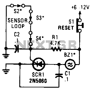
A string of three series-connected, normally closed switches is connected across the gate of a silicon-controlled rectifier (SCR). When one switch opens, the SCR is triggered through resistor R1, activating an alarm. The alarm is designed to be of the...
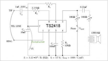
TS2418 Telephone Tone Ringer With Bridge Diode
The TS4956 is a comprehensive audio system device featuring three dedicated outputs: one for stereo headphones, one for loudspeaker drive, and one mono output for a hands-free set. The stereo headphone output can deliver over 25 mW per channel of...
Scr-replacing-latching-switch
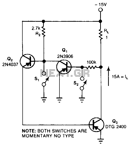
This circuit provides the turn-on characteristics of a Silicon Controlled Rectifier (SCR) but allows for easy turn-off. The switch consists of three transistors with decreasing current ratings: Q3 has a high current rating, while Q2 has a medium rating. The...
SCR UJI TIME DELAY
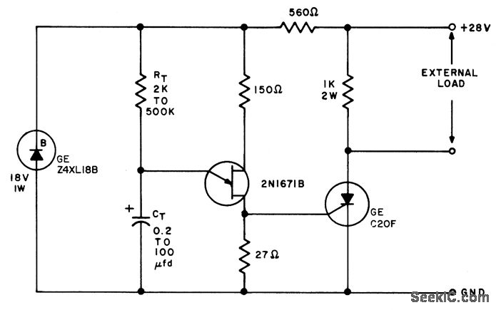
The timing interval is initiated by applying power and is determined by the resistor-capacitor (RT-CT) combination. At the end of the interval, a unijunction transistor triggers a silicon controlled rectifier (SCR) to apply nearly the full supply voltage to the...
Add-on-telephone-hold-button
A sensitive-gate SCR provides a line-holding current of 20 to 40 mA, depending on loop resistance. It also lights an LED to give the user a positive indication that the telephone line is on hold. The 20 to 40 mA...
Stock dial telephone line power supply circuit diagram
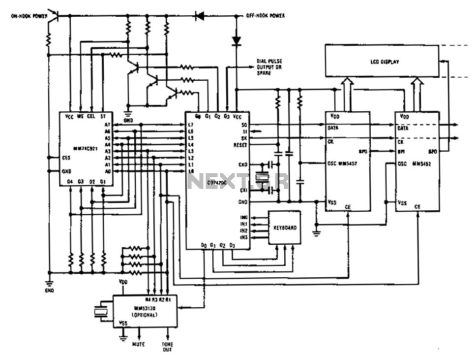
A compilation of dial phone numbers, including 15 commonly used libraries and the dialed number, is stored in standard CMOS RAM. A single-button keypad facilitates the input of a phone number, which can be dialed directly or stored in RAM...
Simple DC power delay circuit
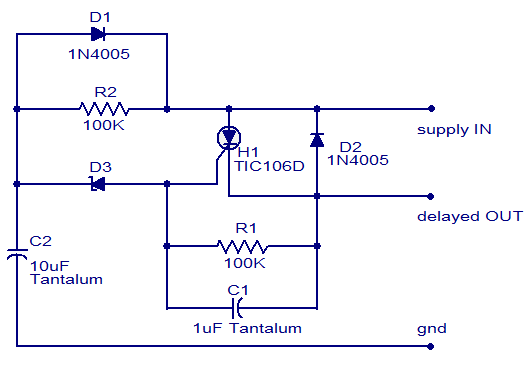
The circuit diagram presented is of a straightforward DC power delay circuit utilizing a silicon-controlled rectifier (SCR). This circuit is quite useful and can be applied in various scenarios. The operation of this circuit is uncomplicated. Upon the application of...
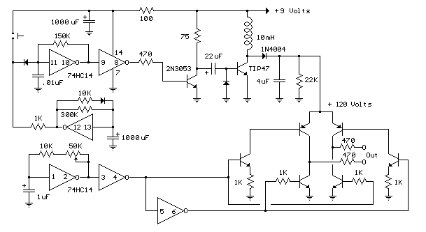
Telephone Ring Generator Using Switching Supply
The telephone ring generator shown below generates the needed high voltage from a simple switching mode power supply (SMPS) which employs a CMOS Schmitt Trigger square wave oscillator, 10 mH inductor, high voltage switching transistor (TIP47 or other high voltage,...
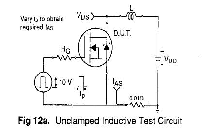
circuits
Uploaded with ImageShack.us Uploaded with ImageShack.us Uploaded with ImageShack.us Inquiry regarding experiences with specific circuits.
In this context, the inquiry pertains to the performance and functionality of certain electronic circuits that have been shared via an image hosting service. The request...