


TheCircuit of One-hour Timing Circuit Using LM122
#LM122
#timing circuit
#switch control
#charging
#discharging
#timer output
#one-hour timer
#electronics
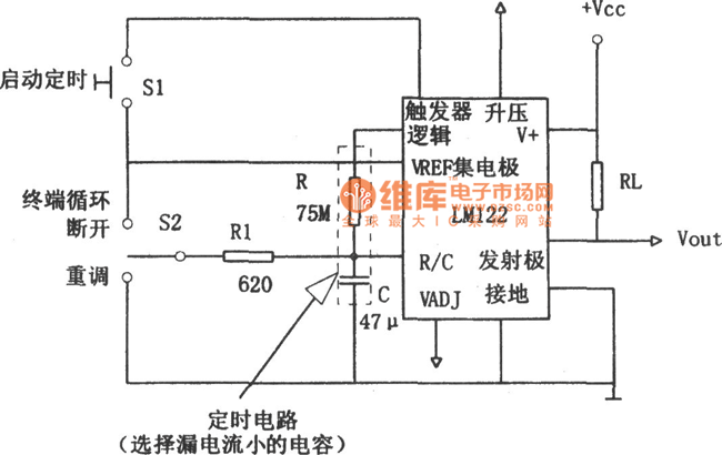
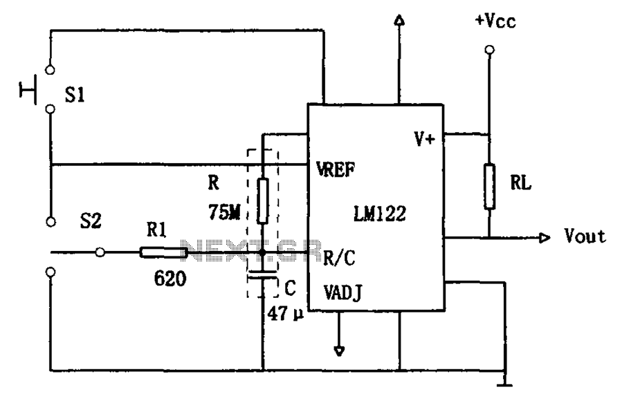
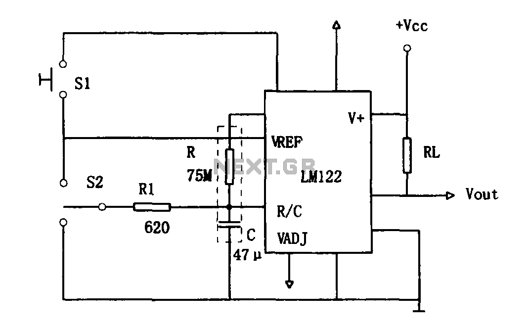
Description: In this figure, S1 initiates the timing process, and once the timer is activated, toggling this switch will not impact the timing operation. S2 serves as the OFF switch located in the center; toggling this switch allows the timer to complete its cycle, which includes charging, transitioning to an open circuit, and discharging. If the charging process is interrupted midway, the charging state will revert to the operational state of the timer's output circuit.
The circuit described incorporates two switches, S1 and S2, which play critical roles in the timer's operation. S1, when engaged, begins the timing sequence, allowing the timer to function without interference. This characteristic is essential for precision timing applications where accidental interruption of the timing sequence must be avoided. The switch S2, positioned centrally, functions as an OFF switch, providing the user with control to halt the timer at any point during its operation.
The timer's operational cycle consists of three distinct phases: charging, open circuit, and discharging. During the charging phase, energy is stored in a capacitor or similar component until a predetermined voltage is reached. The transition to an open circuit indicates that the timer is ready to release its stored energy. In the discharging phase, the stored energy is utilized to perform a specific task, such as activating a relay or powering an output device.
If the charging phase is interrupted—meaning S2 is toggled during this process—the circuit is designed to revert to the operational state of the timer's output. This feature ensures that the timer can resume its function without losing the previous state, thereby enhancing the reliability and efficiency of the circuit in various applications. The careful design of these switches and the timing mechanism is crucial in applications requiring precise control and timing, such as in automated systems, timers, and various electronic devices.In this figure S1 can start timing and when the timer starts, turning this switch has no effect.S2 is the OFF switch in the middle and turning this switch can make the timer complete the procedure: charging-open circuit-discharging. Because of charging stopped halfway, the charging position would return to the work state of the timer s output circuit.
A..
The circuit described incorporates two switches, S1 and S2, which play critical roles in the timer's operation. S1, when engaged, begins the timing sequence, allowing the timer to function without interference. This characteristic is essential for precision timing applications where accidental interruption of the timing sequence must be avoided. The switch S2, positioned centrally, functions as an OFF switch, providing the user with control to halt the timer at any point during its operation.
The timer's operational cycle consists of three distinct phases: charging, open circuit, and discharging. During the charging phase, energy is stored in a capacitor or similar component until a predetermined voltage is reached. The transition to an open circuit indicates that the timer is ready to release its stored energy. In the discharging phase, the stored energy is utilized to perform a specific task, such as activating a relay or powering an output device.
If the charging phase is interrupted—meaning S2 is toggled during this process—the circuit is designed to revert to the operational state of the timer's output. This feature ensures that the timer can resume its function without losing the previous state, thereby enhancing the reliability and efficiency of the circuit in various applications. The careful design of these switches and the timing mechanism is crucial in applications requiring precise control and timing, such as in automated systems, timers, and various electronic devices.In this figure S1 can start timing and when the timer starts, turning this switch has no effect.S2 is the OFF switch in the middle and turning this switch can make the timer complete the procedure: charging-open circuit-discharging. Because of charging stopped halfway, the charging position would return to the work state of the timer s output circuit.
A..
Electronics Projects Circuits
Over 1400 top electronics projects and electronic circuits with photos, datasheets, and easy-to-read schematics, along with explanations of how they work and how to build them.
The collection comprises a vast array of electronics projects suitable for enthusiasts and professionals alike....
Use of one hour LM122 timer circuit
The circuit utilizes an LM122 timer, as illustrated in Figure 1, to manage various timing operations, including starting, resetting, and halting the process midway through. The operation of the circuit is governed by switching mechanisms. Switch S1 initiates the timing...
1-20 minutes a timing circuit
The system operates between 10 minutes to 2 hours, featuring a 100-line bell controlled by a multi-gear stick labeled S2 41f. The integrated circuit (IC) functions as a self-excited multivibrator. The device can manage binary pulses ranging from 3 to...
freeze protector circuit
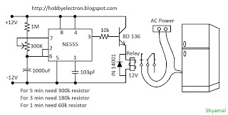
This is a simple freeze protector circuit diagram, also known as a timing circuit. It serves as a hobby project for beginners. This circuit can automatically operate any device after a fixed time once AC power supply is restored. The...
1-20 minutes a timing circuit
The system operates between 10 minutes to 2 hours, featuring a 100-line bell controlled by a multi-gear stick labeled S2 41f. The integrated circuit (IC) functions as a self-excited multivibrator. The device can manage binary pulses ranging from 3 to...
1 hour LM122 timer circuit
As illustrated in Figure 1, the circuit utilizes an LM122 timer. The circuit's start, reset, and stop functions are managed through switching operations. Switch S1 initiates the timing sequence when the timer is activated; thereafter, this switch has no further...
timing circuit
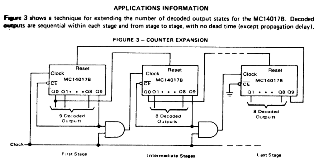
Assistance is needed for the design of a timing circuit intended to activate a spark plug every 10 or 20 revolutions of a shaft.
The timing circuit for firing a spark plug at specified intervals can be designed using a combination...
EGR 450 Manufacturing Controls Project
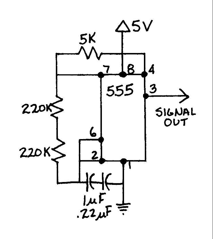
A timing and counting circuit utilizing integrated circuit chips with seven-segment LED displays is employed to show the current lap time, previous lap time, and total number of laps completed on a 1/64th-scale slot car racetrack. A switch activated by...
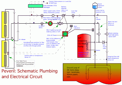
Charging the Earth
The intentions for night air charging have been deemed possible but unnecessary. During late March and early April, the heating system operated effectively at night due to favorable air temperatures compared to glycol temperatures, which proved beneficial. With the arrival...