


555 circuits
#555 timer
#556 timer
#monostable
#pulse generator
#switch control
#ebay
#electronics project
#DIY electronics
#timer circuit
#trigger input
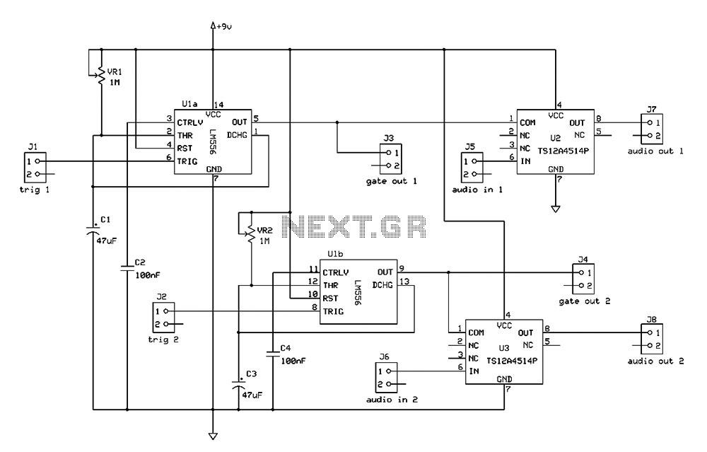
Description: The Switchgate is a simple dual gate circuit based on a 556 timer configured in monostable mode, featuring a trigger input that activates two switches. The outputs of the monostables are also available individually. Recent research has led to the development of the PO-555N, referred to as the Phoenix Oscillator, which utilizes a 555 timer and offers a wider range of operation from low-frequency oscillation (LFO) rates to high audio frequencies, along with enhanced waveshaping capabilities. While it is not compatible with modular synth standards such as 1V/oct control voltage (CV) response, the pitch and rate can be modulated via a CV input. The design includes a fine-tuning knob and a unique tri glitch feature achieved through positive feedback on the saw-to-triangle conversion side of the operational amplifier. Additionally, the Modutronic Messmaker integrates a 555 oscillator for sound synthesis, incorporating an audio input for amplitude modulation (AM). The final circuit includes four jacks for connectivity, with switched jacks allowing for internal input when no external connections are made. Controls for frequency, voltage starvation, and output levels are also present.
The Switchgate design employs a 556 timer, which contains two independent timing circuits, configured in a monostable mode. This configuration allows the circuit to produce a single output pulse when triggered. The trigger input can be activated by an external signal, causing both outputs of the monostables to switch states, which can be utilized in various applications such as gate control in synthesizers or triggering other circuits.
The PO-555N, or Phoenix Oscillator, expands upon the basic functionality of the 555 timer by incorporating additional circuitry to produce a variety of waveforms. The square-to-saw and saw-to-triangle converters are modified versions of existing circuits, offering a broader frequency range than traditional designs. This oscillator allows for creative sound design, particularly in synthesizer applications, where modulation of pitch and timbre is essential. The inclusion of a fine-tuning knob enhances user control over the output frequency, while the tri glitch feature introduces unique sonic characteristics through feedback manipulation.
The Modutronic Messmaker represents a significant evolution in the design, integrating a 555 oscillator to facilitate sound synthesis. The addition of an audio input for AM processing allows for complex sound modulation, enhancing the versatility of the circuit. The schematic indicates the use of 2.2kΩ potentiometers instead of the specified 5kΩ, showcasing a practical approach to component sourcing.
Overall, the circuit features four jacks: a CV input for the 555 oscillator, the output of the 555, an input for the 567 amplitude modulation (pseudo-ring modulation), and the output of the 567. The use of switched jacks ensures that the circuit can operate autonomously when not interfaced with external equipment, allowing for seamless integration into larger synthesizer setups. The user interface includes controls for adjusting the frequency of each oscillator, voltage starvation effects, and output levels, providing comprehensive control over the sound generation process.I`ve decided to start selling these on ebay to raise some money for parts. Here`s a link to the current auction and here`s a photo of the current model: Switchgate is a simple dual gate based on a 556 in monostable mode (with trigger input), with the monostables triggering two switches. The monostable outputs are also accessible via their own outputs. Audio clip: Adobe Flash Player (version 9 or above) is required to play this audio clip. Download the latest version here. You also need to have JavaScript enabled in your browser. Some recent research led me to another conglomeration of circuit snippets, which I`m currently calling the PO-555N (Phoenix Oscillator, 555 based, N for nasty ). The square-to-saw (which you may recognize from the 566 osc) and the saw-to-triangle bits are tweaked versions of circuits found at the Experimentalists Anonymous archives.
This one has a much wider range- from LFO rates to high audio rates- and also adds more waveshaping options. Like the previous 566 osc, this one is not compatible with any modular synth standards (such as 1V/oct CV response), but the pitch/rate can be modulated via CV input.
This one also adds a fine-tuning knob. Audio clip: Adobe Flash Player (version 9 or above) is required to play this audio clip. Download the latest version here. You also need to have JavaScript enabled in your browser. Towards the end (after 2:00-ish), you can also hear the tri glitch feature, which is simply positive feedback through a capacitor on the saw-to-triangle side of the op amp, a little something I came across while messing around. This will be replacing the APC oscillator in Phoenix, which was just there as a placeholder because I wanted more sound sources right away.
I`m also going to be reconfiguring the front panel so that all the controls are on the left, and all the jacks are on the right. So, the plan for the 567 changed a little bit. Meet the Modutronic Messmaker- I added a 555 oscillator to make it a synth (with audio input for the AM part).
Here`s the schematic: I actually used 2. 2k pots where 5k`s are specified in the schemo (more scavanged parts). Here`s what the final circuit looked like before going into a case: There are a total of four jacks- from left in the above picture: 555 CV in, 555 output, 567 AM (pseudo-ring mod) in, 567 out. The inputs use switched jacks, so when nothing is plugged into them, they receive input internally. With no inputs, the 567 is fed from the 555 output, and the 555 CV input is fed from the 567 ²s output.
There are controls for the frequency of each osc, voltage starve, 555 CV input level, 567 output level, an The interesting thinething different, this tieeping from low frequene power`s cycled, vario
The Switchgate design employs a 556 timer, which contains two independent timing circuits, configured in a monostable mode. This configuration allows the circuit to produce a single output pulse when triggered. The trigger input can be activated by an external signal, causing both outputs of the monostables to switch states, which can be utilized in various applications such as gate control in synthesizers or triggering other circuits.
The PO-555N, or Phoenix Oscillator, expands upon the basic functionality of the 555 timer by incorporating additional circuitry to produce a variety of waveforms. The square-to-saw and saw-to-triangle converters are modified versions of existing circuits, offering a broader frequency range than traditional designs. This oscillator allows for creative sound design, particularly in synthesizer applications, where modulation of pitch and timbre is essential. The inclusion of a fine-tuning knob enhances user control over the output frequency, while the tri glitch feature introduces unique sonic characteristics through feedback manipulation.
The Modutronic Messmaker represents a significant evolution in the design, integrating a 555 oscillator to facilitate sound synthesis. The addition of an audio input for AM processing allows for complex sound modulation, enhancing the versatility of the circuit. The schematic indicates the use of 2.2kΩ potentiometers instead of the specified 5kΩ, showcasing a practical approach to component sourcing.
Overall, the circuit features four jacks: a CV input for the 555 oscillator, the output of the 555, an input for the 567 amplitude modulation (pseudo-ring modulation), and the output of the 567. The use of switched jacks ensures that the circuit can operate autonomously when not interfaced with external equipment, allowing for seamless integration into larger synthesizer setups. The user interface includes controls for adjusting the frequency of each oscillator, voltage starvation effects, and output levels, providing comprehensive control over the sound generation process.I`ve decided to start selling these on ebay to raise some money for parts. Here`s a link to the current auction and here`s a photo of the current model: Switchgate is a simple dual gate based on a 556 in monostable mode (with trigger input), with the monostables triggering two switches. The monostable outputs are also accessible via their own outputs. Audio clip: Adobe Flash Player (version 9 or above) is required to play this audio clip. Download the latest version here. You also need to have JavaScript enabled in your browser. Some recent research led me to another conglomeration of circuit snippets, which I`m currently calling the PO-555N (Phoenix Oscillator, 555 based, N for nasty ). The square-to-saw (which you may recognize from the 566 osc) and the saw-to-triangle bits are tweaked versions of circuits found at the Experimentalists Anonymous archives.
This one has a much wider range- from LFO rates to high audio rates- and also adds more waveshaping options. Like the previous 566 osc, this one is not compatible with any modular synth standards (such as 1V/oct CV response), but the pitch/rate can be modulated via CV input.
This one also adds a fine-tuning knob. Audio clip: Adobe Flash Player (version 9 or above) is required to play this audio clip. Download the latest version here. You also need to have JavaScript enabled in your browser. Towards the end (after 2:00-ish), you can also hear the tri glitch feature, which is simply positive feedback through a capacitor on the saw-to-triangle side of the op amp, a little something I came across while messing around. This will be replacing the APC oscillator in Phoenix, which was just there as a placeholder because I wanted more sound sources right away.
I`m also going to be reconfiguring the front panel so that all the controls are on the left, and all the jacks are on the right. So, the plan for the 567 changed a little bit. Meet the Modutronic Messmaker- I added a 555 oscillator to make it a synth (with audio input for the AM part).
Here`s the schematic: I actually used 2. 2k pots where 5k`s are specified in the schemo (more scavanged parts). Here`s what the final circuit looked like before going into a case: There are a total of four jacks- from left in the above picture: 555 CV in, 555 output, 567 AM (pseudo-ring mod) in, 567 out. The inputs use switched jacks, so when nothing is plugged into them, they receive input internally. With no inputs, the 567 is fed from the 555 output, and the 555 CV input is fed from the 567 ²s output.
There are controls for the frequency of each osc, voltage starve, 555 CV input level, 567 output level, an The interesting thinething different, this tieeping from low frequene power`s cycled, vario
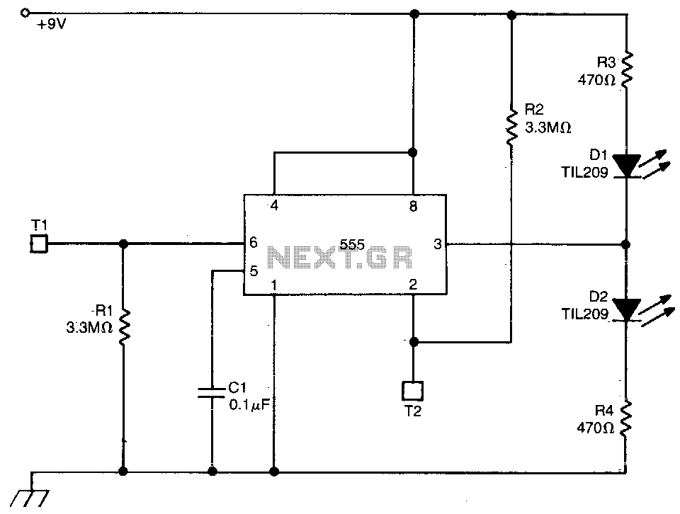
Touch triggered bistable
This circuit employs a 555 timer configured in bistable mode. Activating T2 results in a high output, causing D2 to conduct while D1 turns off. Conversely, activating T1 leads to a low output, with D1 conducting and D2 being cut...
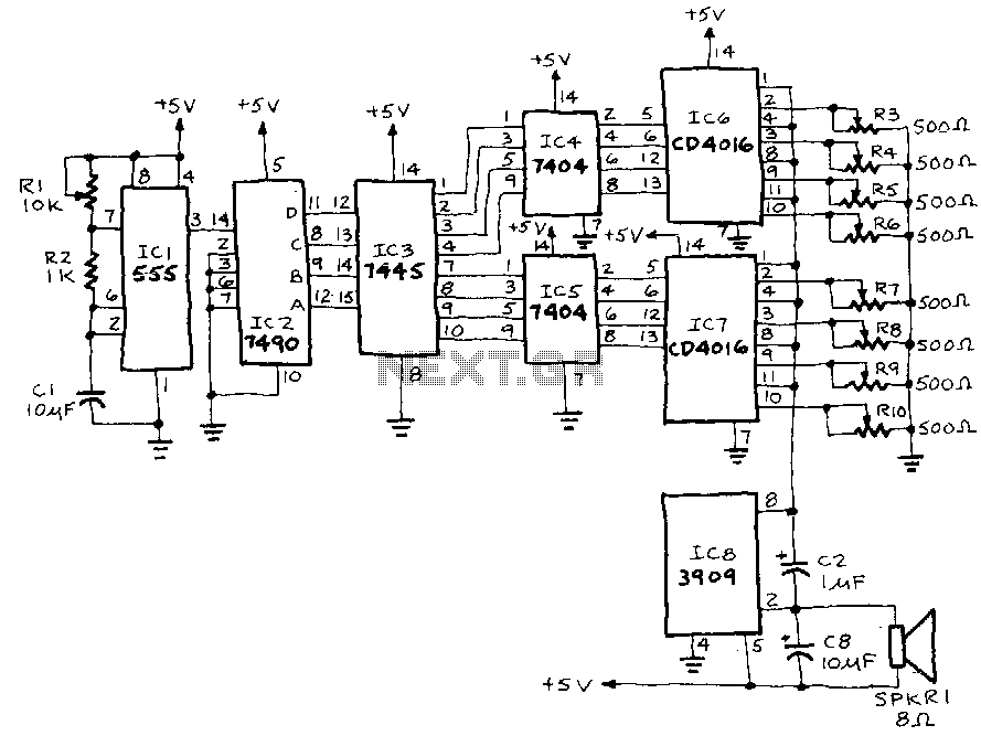
Electronic-music
IC1, a 555 timer, is configured as an astable multivibrator to generate a signal that triggers IC2, a 7490 decade counter. This counter produces a BCD output that is connected to IC3, a 7445 BCD-to-decimal decoder/driver. The output from IC3...
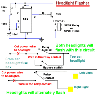
555 Timer For Headlight Flasher
It allows car headlights to flash on and off simultaneously or alternately. Components: 555 IC, transistor, resistor, relay, polarized capacitor.
The circuit utilizes a 555 integrated circuit (IC) in a monostable or astable configuration to control the flashing of car headlights....
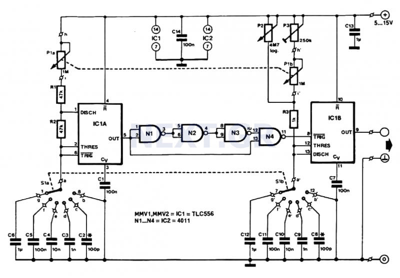
Low Cost Pulse Generator circuit
This pulse generator produces square pulses ranging from 1Hz to 100KHz with an adjustable pulse width of nearly 0-100%. It operates on a voltage of 5-15V, making it suitable for both TTL and CMOS circuits. This device is essential for...
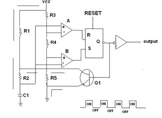
555 timer IC as A-stable Multivibrator
A 555 timer IC is utilized as an astable multivibrator, as illustrated in the accompanying figure (A). The threshold input is connected to the trigger input (Pin 2). The resistor R1, resistor R2, and capacitor C1 form the timing network...
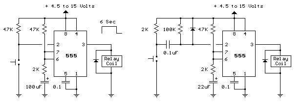
555 timer mono stable one shot circuit
The two circuits below illustrate the application of the 555 timer to activate a relay for a specified duration by pressing a momentary normally open (N/O) push button. The circuit on the left can be used for longer time periods...
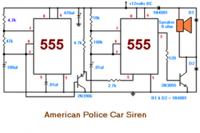
American Police Car Siren by IC 555
The second circuit simulates the siren of an American police car. It utilizes two 555 timers. The 555 timer on the right is configured as an alarm tone generator, while the second 555 timer on the left operates as a...
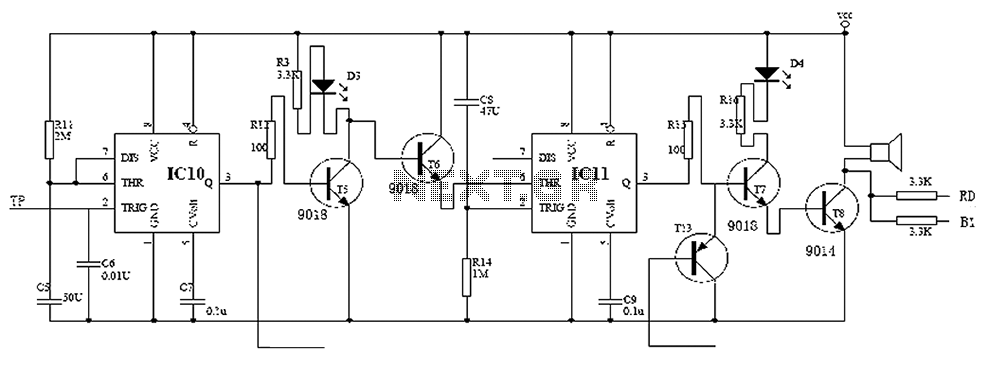
Electronic locks 555 monostable circuit diagram
Child lock voltage comparator 555 monostable circuit, a counter, JK flip-flop, UPS power supply design digital logic circuit, electronic door control, and various additional circuitry to ensure the safety circuit can operate with a high safety factor. The circuit allows...

Schematic Diagram Trigger Input Control Of 555 Timers
The following method allows the timer to be triggered by a normally closed switch. This would be useful in applications such as intrusion alarms where the protection circuit is broken if a window or door is opened. Trigger Input Control...