


Downbeat-emphasized-electronic-metronome
#metronome
#astable multivibrator
#4017B decade counter
#clock pulse
#electronic timing
#pulse generation
#downbeat
#counter circuit
#reset input
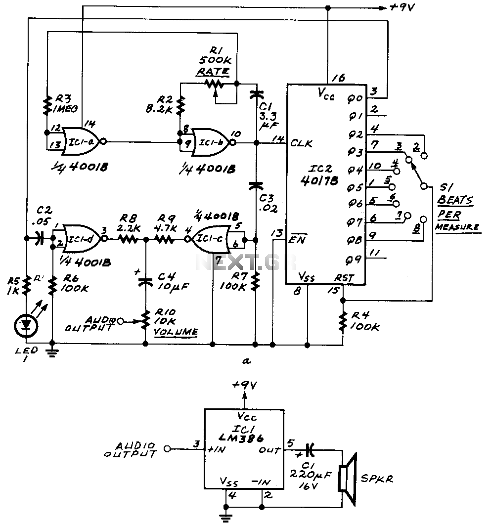
Description: ICla and IClb form an astable multivibrator. The astable's signal is fed to IC1c, as well as to the clock input of IC2, a 4017B decade counter. The outputs Q0 through Q9 of that IC become high one at a time for each successive clock pulse received at pin 14. Switch S1 feeds one of those outputs to the reset input of the 4017B. Whenever the selected output becomes high, the 4017B restarts its counting cycle, which determines the number of beats per measure. The network composed of C2 and R6 sharpens the downbeat pulse, while the network composed of C3 and R7 sharpens the free-running pulses. By making C2 larger than C3, the downbeat receives greater emphasis.
The circuit utilizes an astable multivibrator formed by operational amplifiers ICla and IClb, generating a continuous square wave output. This signal is routed to IC1c, which serves as an intermediary stage before driving the clock input of the 4017B decade counter (IC2). The 4017B is designed to count in a sequential manner, activating its output pins Q0 through Q9 sequentially with each clock pulse received at pin 14. The functionality of the circuit is enhanced by the inclusion of switch S1, which allows for the selection of one of the decade counter's outputs to be connected to its reset input.
This reset feature is crucial, as it permits the 4017B to restart its counting cycle upon receiving a high signal from the selected output. This action effectively controls the number of beats per measure in a musical or timing application. The circuit also incorporates two RC networks, one comprising capacitor C2 and resistor R6, and the other consisting of capacitor C3 and resistor R7. These networks are designed to condition the pulse signals: the first network enhances the downbeat pulse, while the second sharpens the free-running pulses.
The design choice to make capacitor C2 larger than C3 is intentional, as it provides a more pronounced downbeat, which can be particularly beneficial in musical applications where clear rhythmic emphasis is desired. The overall configuration of this circuit allows for precise timing control and rhythmic pattern generation, making it suitable for various electronic applications that require counting and pulse generation.ICla and IClb form an astable multivibrator. The astable"s signal is fed to IC1c, also to the clock input of IC2, a 4017B decade counter. That IC"s QO through Q9 outputs become high one at a time for each successive clock pulse received at1Jin 14. Switch Sl feeds one of those outputs to the 4017B"s reset input. Whenever the selected output becomes high, the 4017B restarts its counting cycle; that determines the number of beats per measure. The network composed of C2 and R6 sharpens the ~downbeat pulse, and the network composed of C3 and R7 sharpens the free-running pulses.
By making C2 larger than C3, the downbeat receives greater emphasis.
The circuit utilizes an astable multivibrator formed by operational amplifiers ICla and IClb, generating a continuous square wave output. This signal is routed to IC1c, which serves as an intermediary stage before driving the clock input of the 4017B decade counter (IC2). The 4017B is designed to count in a sequential manner, activating its output pins Q0 through Q9 sequentially with each clock pulse received at pin 14. The functionality of the circuit is enhanced by the inclusion of switch S1, which allows for the selection of one of the decade counter's outputs to be connected to its reset input.
This reset feature is crucial, as it permits the 4017B to restart its counting cycle upon receiving a high signal from the selected output. This action effectively controls the number of beats per measure in a musical or timing application. The circuit also incorporates two RC networks, one comprising capacitor C2 and resistor R6, and the other consisting of capacitor C3 and resistor R7. These networks are designed to condition the pulse signals: the first network enhances the downbeat pulse, while the second sharpens the free-running pulses.
The design choice to make capacitor C2 larger than C3 is intentional, as it provides a more pronounced downbeat, which can be particularly beneficial in musical applications where clear rhythmic emphasis is desired. The overall configuration of this circuit allows for precise timing control and rhythmic pattern generation, making it suitable for various electronic applications that require counting and pulse generation.ICla and IClb form an astable multivibrator. The astable"s signal is fed to IC1c, also to the clock input of IC2, a 4017B decade counter. That IC"s QO through Q9 outputs become high one at a time for each successive clock pulse received at1Jin 14. Switch Sl feeds one of those outputs to the 4017B"s reset input. Whenever the selected output becomes high, the 4017B restarts its counting cycle; that determines the number of beats per measure. The network composed of C2 and R6 sharpens the ~downbeat pulse, and the network composed of C3 and R7 sharpens the free-running pulses.
By making C2 larger than C3, the downbeat receives greater emphasis.
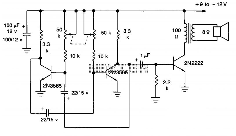
Metronome II
This simple circuit utilizes a multivibrator to generate beats, followed by an audio amplifier stage to enhance the output level. The range of adjustment is approximately from 40 to 200 beats per minute, controlled by a gauged potentiometer.
The described circuit...
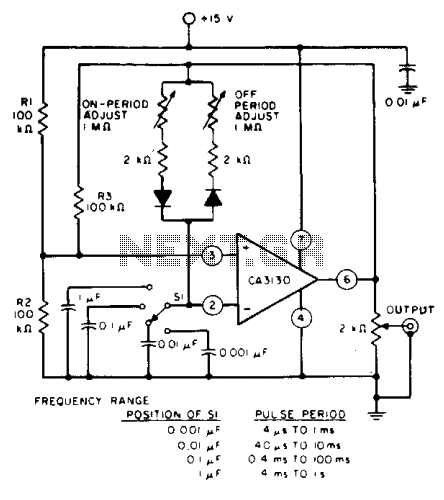
Astable multivibrator IIV
The circuit features independent control of "ON" and "OFF" periods and employs the CA3130 BiMOS operational amplifier for various applications, including filters, oscillators, and long-duration timers. It operates with an input current of 50 pA, allowing oscillators to utilize large...
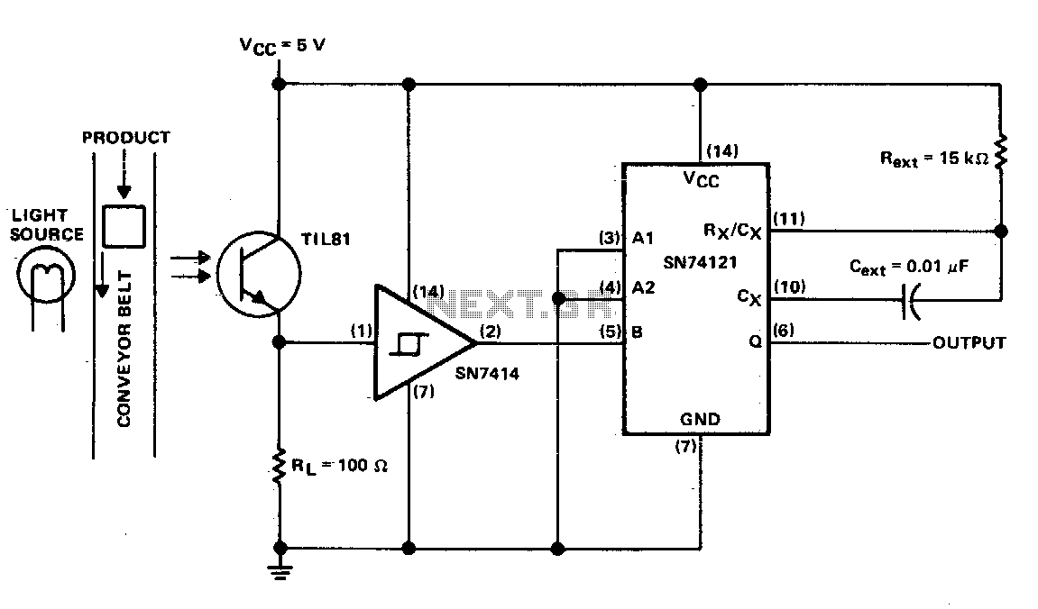
Pulse generation by interrupting a light beam
This circuit generates a pulse when an object on the conveyor belt obstructs the light source. The light source continuously keeps the phototransistor activated, resulting in a high logic level voltage at the Schmitt-trigger inverter and a TTL-compatible low logic...
Binary circuit diagram box
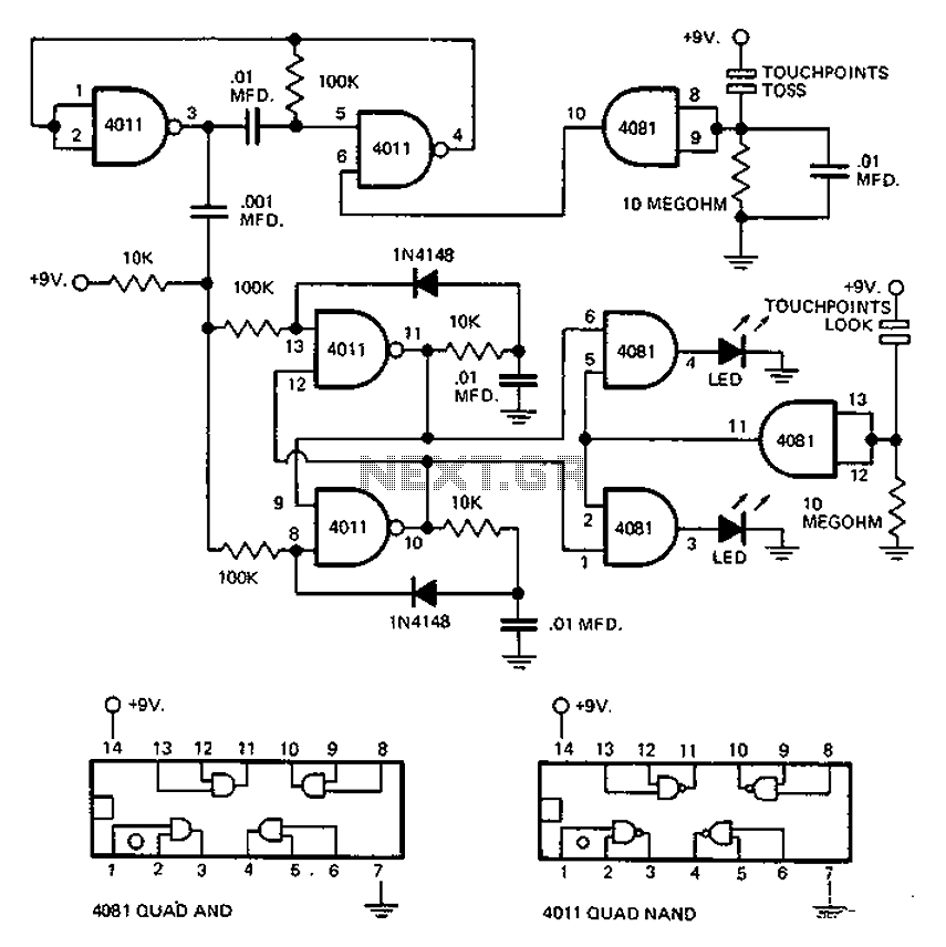
This circuit employs an astable multivibrator to alter the state of a signal based on specific conditions. It also incorporates a flip-flop, which retains the state of the output once a change is detected, completing a cycle of the oscillator.
The...
Astable multivibrator-2 LED flashing circuit2N39043.7V
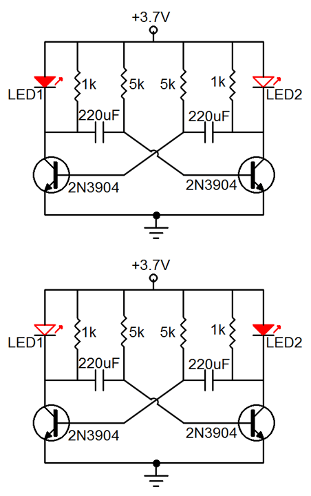
Many friends have requested an automatic on/off LED circuit or an LED flashing circuit. This post presents an astable multivibrator circuit designed for LED flashing. It is a simple astable multivibrator circuit utilizing two LEDs (specifically red LEDs) and two...

Simple Electronic Metronome
Metronome is an electronic device that keeps rhythm by making regulated clicking sounds, device used to keep the beat while playing a musical instrument. The circuit is an old design to build, but you will find it useful.
The metronome circuit...
Astable Multivibrator I Circuit
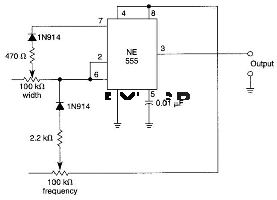
In this multivibrator circuit, frequency and pulse width can be separately controlled by using steering diodes (1N914) and two potentiometers.
This multivibrator circuit utilizes steering diodes, specifically the 1N914 type, to enable independent control over both the frequency and pulse width...

Make this Astable Multivibrator Blinker Circuit Using NAND Gates
An astable multivibrator is an electronic configuration that generates continuous alternating high and low pulses from two outputs operating in tandem. The IC 4093 consists of four individual NAND gates in one package, specifically Schmitt trigger types, which provide hysteresis...
Circuit operation explanation of astable multivibrator
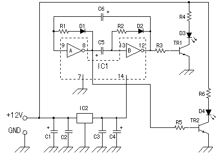
The circuit does not fail under slight variations, even if the input/output electric current characteristics are exceeded. Failure occurs only during a short circuit or extreme conditions at the output. The operation of the circuit is explained as follows: the...