


one second audible clock
#CMos 4024
#counter
#divider
#metronome
#time-delay
#frequency divider
#beep
#flash
#timer circuit
#pulse generator
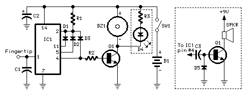
Description: A beep or metronome-like click and/or a visible flash will indicate a one-second interval, which can be useful in various applications requiring time-delay counting in seconds. The circuit utilizes a CMOS 4024 counter/divider chip and three diodes, configured to divide the frequency of the input signal at pin #1 by 50 (or 60, depending on the notes). The input impedance at pin #1 is very high, so simply touching the pin (or a short track or piece of wire connected to it) is typically sufficient to provide the necessary input signal. An alternative method to supply an input signal involves wrapping a piece of wire several times around any convenient mains cable or transformer. No additional connections are necessary. To ensure precise circuit operation in locations where the mains supply frequency is rated at 60Hz, the circuit must be modified as follows: disconnect the cathode of D1 from pin #11 of IC1 and connect it to pin #9. Additionally, include another 1N4148 diode, connecting its anode to R1 and the cathode to pin #6 of IC1; this completes the modification. The visual display, consisting of D4 and R3, is optional. It is important to note that the value of R3 indicated in the parts list is suitable for low battery voltages. If using 9V or higher voltages, adjust its value to 1K.
The described circuit serves as a timing mechanism, providing a one-second output signal through auditory and visual indicators. The primary component, the CMOS 4024 counter/divider chip, is capable of counting and dividing frequencies, making it ideal for applications that require precise timing intervals. The high input impedance at pin #1 facilitates easy signal input, allowing for straightforward activation by simply touching the pin or using a wire.
In practical implementation, the circuit can be powered by a range of battery voltages, although careful consideration must be given to the resistor values, particularly R3, to ensure proper functionality across different voltage levels. The optional visual display, formed by the LED (D4) and resistor (R3), enhances user interaction by providing a visual cue in addition to the audible beep or click.
The modifications for 60Hz operation involve critical changes to the diode connections, ensuring that the circuit remains functional in environments where the mains frequency differs from the standard 50Hz. This adaptability allows the circuit to be utilized in various geographical locations without compromising performance.
Overall, this circuit design is versatile and can be easily modified to suit specific requirements, making it suitable for applications ranging from educational tools to industrial timing solutions.A beep or metronome-like click and/or a visible flash, will beat the one-second time and can be useful in many applications in which some sort of time-delay counting in seconds is desirable. The circuit is formed by a CMos 4024 counter/divider chip and 3 diodes, arranged to divide the frequency of the input signal at pin #1 by 50 (or 60, see Notes
). The input impedance at pin #1 is very hight, so simply touching the pin (or a short track or piece of wire connected to it) is usually enough to provide the necessary input signal. Another way to provide an input signal consists in a piece of wire wrapped several times around any convenient mains cable or transformer.
No other connection is necessary. To allow precise circuit operation in places where the mains supply frequency is rated at 60Hz, the circuit must be modified as follows: disconnect the Cathode of D1 from pin #11 of IC1 and connect it to pin #9. Add a further 1N4148 diode, connecting its Anode to R1 and the Cathode to pin #6 of IC1: that`s all! The visual display, formed by D4 and R3 is optional. Please note that R3 value shown in the Parts list is suited to low battery voltages. If 9V or higher voltages are used, change its value to 1K.
The described circuit serves as a timing mechanism, providing a one-second output signal through auditory and visual indicators. The primary component, the CMOS 4024 counter/divider chip, is capable of counting and dividing frequencies, making it ideal for applications that require precise timing intervals. The high input impedance at pin #1 facilitates easy signal input, allowing for straightforward activation by simply touching the pin or using a wire.
In practical implementation, the circuit can be powered by a range of battery voltages, although careful consideration must be given to the resistor values, particularly R3, to ensure proper functionality across different voltage levels. The optional visual display, formed by the LED (D4) and resistor (R3), enhances user interaction by providing a visual cue in addition to the audible beep or click.
The modifications for 60Hz operation involve critical changes to the diode connections, ensuring that the circuit remains functional in environments where the mains frequency differs from the standard 50Hz. This adaptability allows the circuit to be utilized in various geographical locations without compromising performance.
Overall, this circuit design is versatile and can be easily modified to suit specific requirements, making it suitable for applications ranging from educational tools to industrial timing solutions.A beep or metronome-like click and/or a visible flash, will beat the one-second time and can be useful in many applications in which some sort of time-delay counting in seconds is desirable. The circuit is formed by a CMos 4024 counter/divider chip and 3 diodes, arranged to divide the frequency of the input signal at pin #1 by 50 (or 60, see Notes
). The input impedance at pin #1 is very hight, so simply touching the pin (or a short track or piece of wire connected to it) is usually enough to provide the necessary input signal. Another way to provide an input signal consists in a piece of wire wrapped several times around any convenient mains cable or transformer.
No other connection is necessary. To allow precise circuit operation in places where the mains supply frequency is rated at 60Hz, the circuit must be modified as follows: disconnect the Cathode of D1 from pin #11 of IC1 and connect it to pin #9. Add a further 1N4148 diode, connecting its Anode to R1 and the Cathode to pin #6 of IC1: that`s all! The visual display, formed by D4 and R3 is optional. Please note that R3 value shown in the Parts list is suited to low battery voltages. If 9V or higher voltages are used, change its value to 1K.
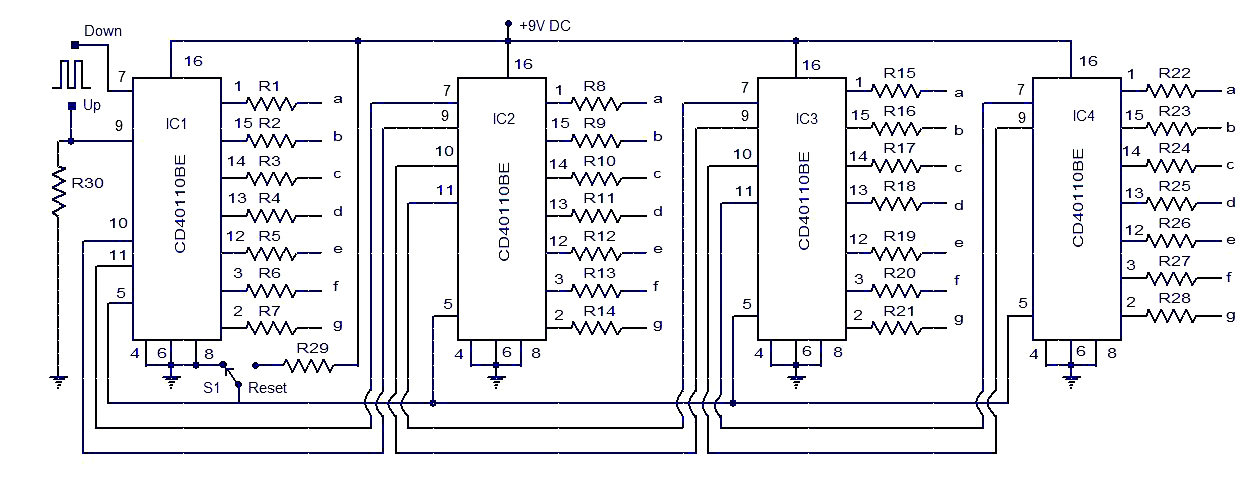
up down counter circuit
This circuit diagram illustrates a simple up/down counter suitable for various applications. It utilizes the CD40110BE IC, a CMOS decade up/down counter. Common cathode seven-segment displays are connected to the outputs of each IC. The display connected to IC1 shows...
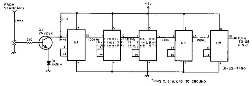
Frequency Divider For Measurements Circuit
This circuit is designed to be driven by a 1-MHz standard signal with an amplitude of several volts. The components U1 through U5 are 7490 decade counters/dividers, providing a division ratio of 100,000:1. It is possible to tap off successive...
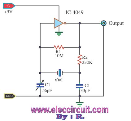
Pulse Generator Oscillator 32.768KHz by watch crystal
A friend requires a pulse generator oscillator circuit that maintains a stable frequency of 32.768 kHz for a digital CMOS binary counter.
The pulse generator oscillator circuit designed to operate at a frequency of 32.768 kHz is commonly used in digital...
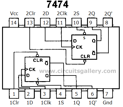
Ring Counter Circuit Working Principle with Animation and Video
Digital counters have various applications in electronic circuits. In digital electronics, counters are utilized in different situations. This article presents the concept of a ring counter circuit, which functions as a register counter. An animation and simulation video of the...
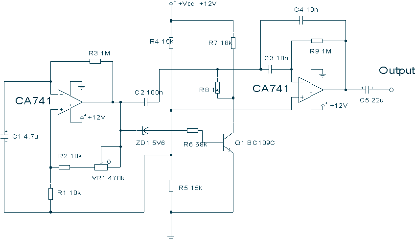
Metronome with CA741
This circuit uses a couple of Op-amps to produce an interesting sound effect. The left hand CA741 is wired as a standard astable and produces the timing pulses, controlled by C1, R2 and VR1. The output is fed via C2...
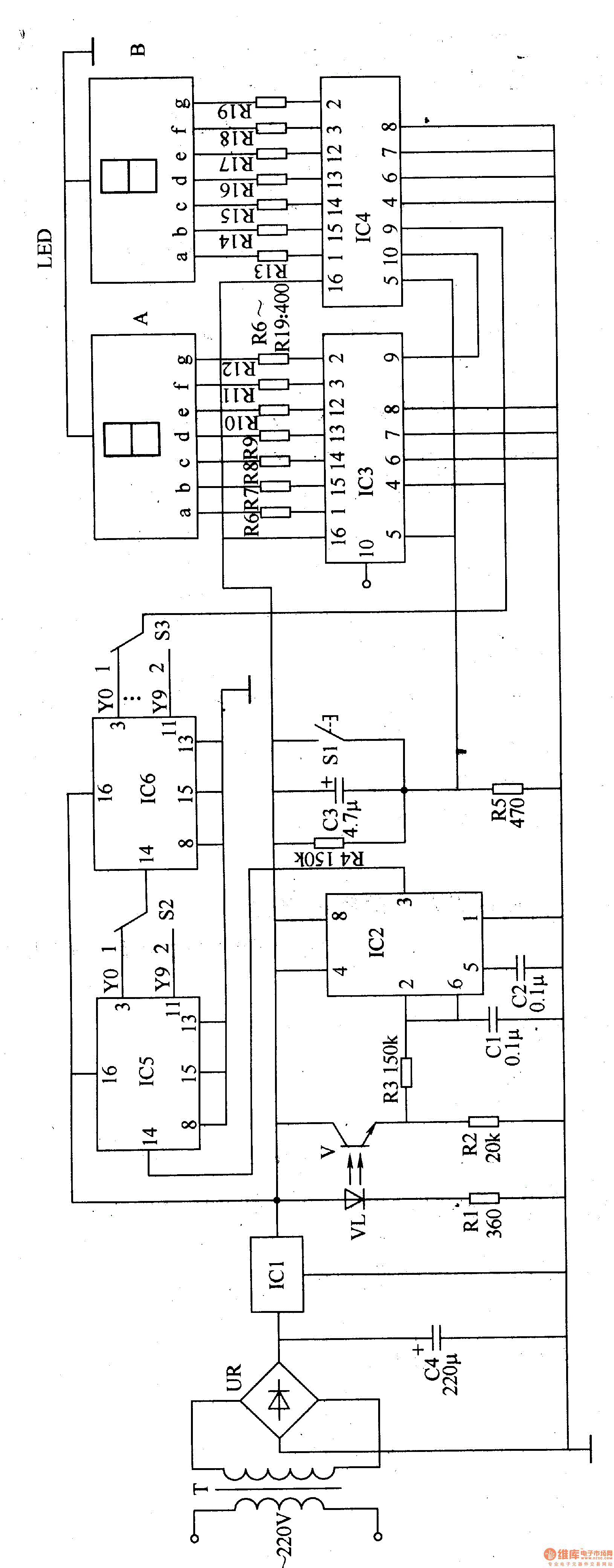
Winding electronic counter 2
The electronic counter of the winding machine utilizes an LED digital display to indicate the number of turns of the wound coil, with a maximum counting capacity of 9900 turns. The operational principle of the winding machine circuit consists of...
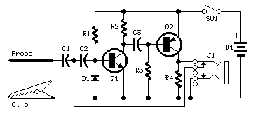
Pulse-Generator & Signal-Tracer
This simple circuit generates narrow pulses at about 700-800Hz frequency. The pulses, containing harmonics up to the MHz region, can be injected into audio or radio-frequency stages of amplifiers, receivers and the like for testing purposes. A high-pitched tone can...
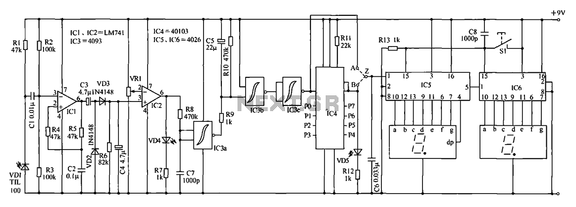
Counter circuit diagram of the digital circuit
The digital counter circuit described utilizes an infrared signal to detect moving targets, making it suitable for counting small devices on a production line as they move along a conveyor belt. This circuit can also be employed for various other...
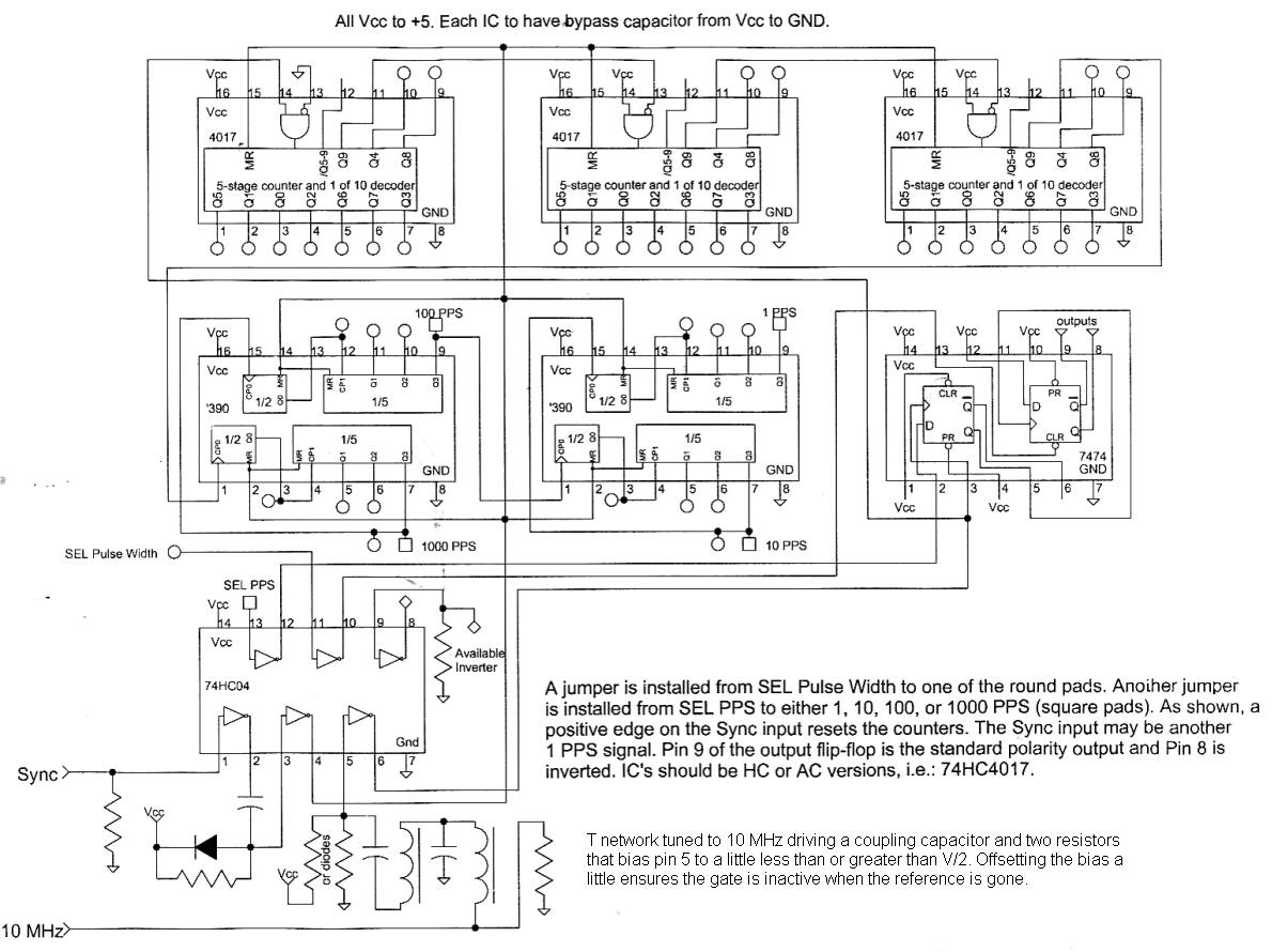
About Area 50
This circuit divides a 10 MHz reference signal to produce outputs of 1, 10, 100, or 1000 pulses per second. The pulse width can be selected using jumpers, offering multiple options. A synchronization input aligns the output pulses with an...