


LDO Regulator -
#LDO
#LM2941
#voltage regulation
#adjustable output
#1A output
#power supply
#circuit schematic
#low dropout
#DC-DC
#electronics
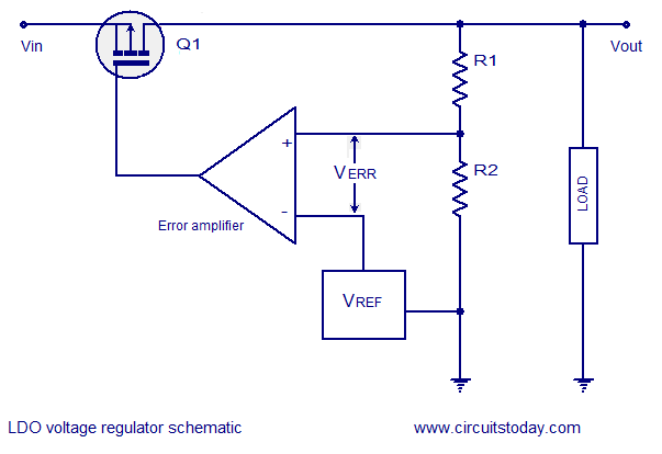
Description: LDO regulators - basic theory, circuit schematic, practical LDO regulator circuit using LM2941 with an adjustable output voltage from 5 to 20V and a maximum output current of 1A.
LDO (Low Dropout) regulators are essential components in power management systems, allowing for the regulation of output voltage with minimal input-output voltage differential. They are characterized by their ability to maintain a steady output voltage despite variations in input voltage and load conditions. The LM2941 is a popular LDO regulator that offers adjustable output voltages ranging from 5V to 20V and can deliver a maximum output current of 1A.
In a typical application, the LM2941 can be configured using a few external resistors to set the desired output voltage. The circuit typically includes input and output capacitors to ensure stability and transient response. The input capacitor is necessary to filter any high-frequency noise from the power supply, while the output capacitor helps in maintaining stability during load transients.
The basic schematic for an LM2941-based LDO circuit includes the following components:
1. **LM2941 Regulator**: This is the central component that regulates the output voltage. It features a built-in thermal shutdown and current limiting for protection against overload conditions.
2. **Input Capacitor (C1)**: A capacitor, typically around 0.33µF, is placed at the input to filter out high-frequency noise and to stabilize the input voltage.
3. **Output Capacitor (C2)**: A capacitor, usually 10µF or greater, is connected at the output to enhance stability and transient response. The output capacitor should have a low equivalent series resistance (ESR) to ensure optimal performance.
4. **Feedback Resistors (R1, R2)**: Two resistors are used to set the output voltage. The values of these resistors can be calculated using the formula provided in the LM2941 datasheet. The output voltage (Vout) is determined by the ratio of these resistors.
5. **Bypass Capacitor (C3)**: A small capacitor (e.g., 0.1µF) may also be included between the adjust pin and ground to improve transient response.
The LM2941 is suitable for various applications, including powering microcontrollers, sensors, and other low-power devices that require a stable voltage supply. Its ability to function effectively with a low dropout voltage makes it ideal for battery-operated devices, where maintaining efficiency is crucial.
Overall, the LM2941 LDO regulator circuit exemplifies a straightforward yet effective design for achieving regulated output voltages across a range of applications, ensuring stable performance and reliability.LDO regulators- basic theory, circuit schematic, practical LDO regulator circuit using LM2941 5 to 20V adjustable o/p ,1A output current..
LDO (Low Dropout) regulators are essential components in power management systems, allowing for the regulation of output voltage with minimal input-output voltage differential. They are characterized by their ability to maintain a steady output voltage despite variations in input voltage and load conditions. The LM2941 is a popular LDO regulator that offers adjustable output voltages ranging from 5V to 20V and can deliver a maximum output current of 1A.
In a typical application, the LM2941 can be configured using a few external resistors to set the desired output voltage. The circuit typically includes input and output capacitors to ensure stability and transient response. The input capacitor is necessary to filter any high-frequency noise from the power supply, while the output capacitor helps in maintaining stability during load transients.
The basic schematic for an LM2941-based LDO circuit includes the following components:
1. **LM2941 Regulator**: This is the central component that regulates the output voltage. It features a built-in thermal shutdown and current limiting for protection against overload conditions.
2. **Input Capacitor (C1)**: A capacitor, typically around 0.33µF, is placed at the input to filter out high-frequency noise and to stabilize the input voltage.
3. **Output Capacitor (C2)**: A capacitor, usually 10µF or greater, is connected at the output to enhance stability and transient response. The output capacitor should have a low equivalent series resistance (ESR) to ensure optimal performance.
4. **Feedback Resistors (R1, R2)**: Two resistors are used to set the output voltage. The values of these resistors can be calculated using the formula provided in the LM2941 datasheet. The output voltage (Vout) is determined by the ratio of these resistors.
5. **Bypass Capacitor (C3)**: A small capacitor (e.g., 0.1µF) may also be included between the adjust pin and ground to improve transient response.
The LM2941 is suitable for various applications, including powering microcontrollers, sensors, and other low-power devices that require a stable voltage supply. Its ability to function effectively with a low dropout voltage makes it ideal for battery-operated devices, where maintaining efficiency is crucial.
Overall, the LM2941 LDO regulator circuit exemplifies a straightforward yet effective design for achieving regulated output voltages across a range of applications, ensuring stable performance and reliability.LDO regulators- basic theory, circuit schematic, practical LDO regulator circuit using LM2941 5 to 20V adjustable o/p ,1A output current..
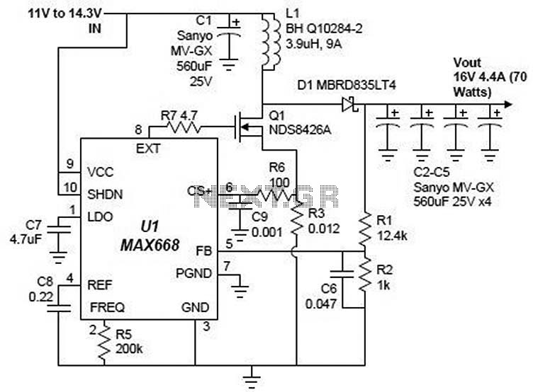
MAX668 16V 4.4A switching power supply circuit design electronic project
A simple 16-volt switching power supply circuit can be constructed using the provided diagram, which is based on the MAX668 constant-frequency, pulse-width modulating (PWM), current-mode DC-DC controller. This integrated circuit is designed for a wide range of DC-DC conversion applications...
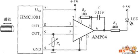
LOW DROPOUT THREE TERMINAL REGULATORS
After the battery is connected, the movement of the touch stick activates the light source, which illuminates the photosensitive tube and generates a light current. This triggers the first level 3DG6 to turn on, allowing the emitter to output a...
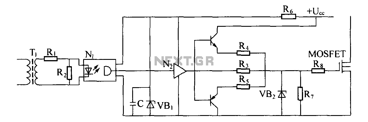
Switching power supply drive circuit
Driver circuit diagram: The primary function of the driver circuit is to serve as a variable width pulse width modulator output power amplifier, providing a drive signal to high voltage power switching devices. The driving circuit typically plays a role...
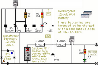
Circuit Diagram Of Alarm Power Supply
The following circuit illustrates an Alarm Power Supply Circuit Diagram. Features include a 1-amp current output, suitable for a Modular Burglar Alarm operating at 12 volts.
The Alarm Power Supply Circuit is designed to provide a stable and reliable power source...
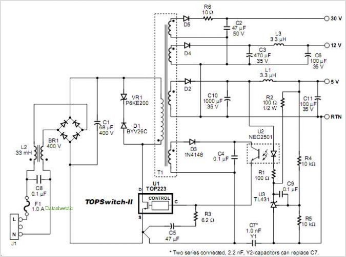
Designing Multiple Output Power Supplies With Topswitch
This application note describes a digital blood pressure meter concept that utilizes integrated pressure sensor analog signal-conditioning circuitry, microcontroller hardware/software, and a liquid crystal display. The sensing system measures cuff pressure (CP) and extracts pulses for analysis to determine systolic...
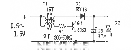
DCDC single cell flashlight drive circuit diagram
This is a simple and easy-to-build DC-DC driver circuit designed for a single flashlight battery, operating at a parametric voltage of 1.5V. The input current is 90mA, while the light-emitting diode (LED) current is 26mA or higher. The circuit can...
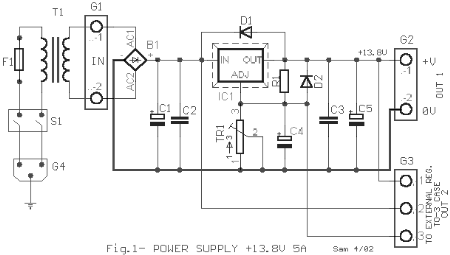
Circuit diagrams and Schematic
This AC to DC power supply can output 5A in continuous operation and 12A peak current. This type of DC power supply uses a PCB, allowing for two case types for IC1: TO-220 or TO-3. The regulation of this 12-volt...
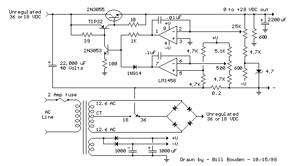
Current and Variable Voltage Power Supply
Another adjustment of application operational amplifiers to adapt a power supply is apparent below. The power supply requires an additional adjustment to supply the op-amps with a bipolar voltage (+/- 8 volts), and the negative voltage is also used to...
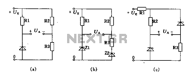
Bridge voltage regulator circuit diagram using the
The circuit depicted in Figures A, B, and C demonstrates a high voltage coefficient. When the regulator resistance \( r_z \) is held constant, the bridge configuration achieves an infinite voltage coefficient. In Figure A, the load circuit is connected...