


Output Stabilizer
#output stabilizer
#SMPS
#dc-to-dc converter
#voltage regulation
#optically isolated
#power supply
#voltage variance
#transmission change
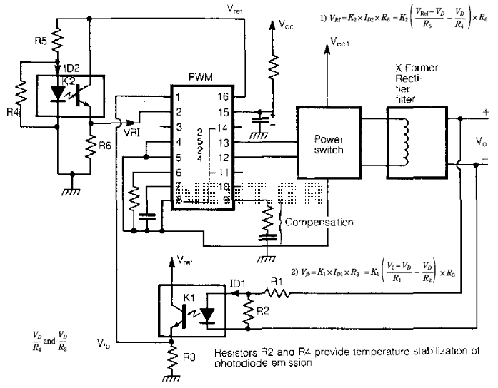
Description: Optically isolated switch-mode power supplies (SMPS) and DC-to-DC converters experience variations in output voltage due to changes in the transmission characteristics of an optoisolator influenced by (a) temperature and (b) aging. The emission from the photodiode diminishes with temperature and over time, leading to fluctuations in output voltage. This issue is addressed using a homoeopathic principle. An additional optical isolator is employed to derive the +Vt input voltage, rather than utilizing a conventional potential divider from an internally stabilized reference. The negative voltage temperature coefficient of VD ensures that any variations in K1 and K2 due to temperature and aging are correlated, thereby maintaining a constant output voltage. With appropriate selection of R2 and i4, the output voltages can be kept within a variance of less than 0.01% per °C across a broad temperature range.
Optically isolated switch-mode power supplies (SMPS) and DC-to-DC converters are essential components in modern electronic systems, providing stable voltage outputs despite fluctuations in input conditions. The performance of these converters can be significantly affected by the characteristics of optoisolators, particularly in terms of temperature variations and aging effects. The photodiode within the optoisolator, which is responsible for transferring the signal, exhibits a decline in emission efficiency as temperature increases and over prolonged usage. This decay can lead to undesirable changes in the output voltage, potentially compromising the performance of the entire circuit.
To mitigate these issues, a homoeopathic principle is applied, which involves the use of an additional optical isolator to derive the positive input voltage (+Vt). This method diverges from traditional designs that typically utilize a potential divider sourced from an internally stabilized reference voltage. By implementing this additional isolator, the circuit achieves improved stability and reliability in its output.
Moreover, the negative voltage temperature coefficient (Ve) of the voltage divider (VD) plays a crucial role in ensuring that variations in the circuit components, K1 and K2, which are influenced by temperature and aging, remain synchronized. This tracking behavior is vital for maintaining a consistent output voltage, as it minimizes the effects of component drift over time.
For optimal performance, careful selection of resistor values (R2) and current (i4) is critical. By fine-tuning these parameters, the design can achieve an impressive output voltage stability, with variations kept to less than 0.01% per °C across a wide temperature spectrum. This level of precision is particularly advantageous in applications where stable voltage supply is paramount for the operation of sensitive electronic components. Overall, the design approach not only enhances the reliability of the power supply but also extends its operational lifespan, ensuring that the performance remains consistent even under challenging environmental conditions. Optically isolated SMPS and dc-to-dc converters face the variance of output voltage owing to the change of transmission c haracteristics of an optoisolator with (a) temperature and (b) aging. The photo diode emission decays with temperature and time, and causes the output voltage to change. The problem is solved using a homoeopathic principle. An additional optical isolator is used to derive the + Vt input voltage, instead of a conventional potential divider from internally stabilized reference. Thanks to - Ve temperature coefficient of VD any changes in K1 and K2 as a result of temperature and aging, track each other to maintain the output voltage constant.
With proper selection of R2 and i4, the output voltages are found to vary by less than 0.01%/°C over a wide temperature range.
Optically isolated switch-mode power supplies (SMPS) and DC-to-DC converters are essential components in modern electronic systems, providing stable voltage outputs despite fluctuations in input conditions. The performance of these converters can be significantly affected by the characteristics of optoisolators, particularly in terms of temperature variations and aging effects. The photodiode within the optoisolator, which is responsible for transferring the signal, exhibits a decline in emission efficiency as temperature increases and over prolonged usage. This decay can lead to undesirable changes in the output voltage, potentially compromising the performance of the entire circuit.
To mitigate these issues, a homoeopathic principle is applied, which involves the use of an additional optical isolator to derive the positive input voltage (+Vt). This method diverges from traditional designs that typically utilize a potential divider sourced from an internally stabilized reference voltage. By implementing this additional isolator, the circuit achieves improved stability and reliability in its output.
Moreover, the negative voltage temperature coefficient (Ve) of the voltage divider (VD) plays a crucial role in ensuring that variations in the circuit components, K1 and K2, which are influenced by temperature and aging, remain synchronized. This tracking behavior is vital for maintaining a consistent output voltage, as it minimizes the effects of component drift over time.
For optimal performance, careful selection of resistor values (R2) and current (i4) is critical. By fine-tuning these parameters, the design can achieve an impressive output voltage stability, with variations kept to less than 0.01% per °C across a wide temperature spectrum. This level of precision is particularly advantageous in applications where stable voltage supply is paramount for the operation of sensitive electronic components. Overall, the design approach not only enhances the reliability of the power supply but also extends its operational lifespan, ensuring that the performance remains consistent even under challenging environmental conditions. Optically isolated SMPS and dc-to-dc converters face the variance of output voltage owing to the change of transmission c haracteristics of an optoisolator with (a) temperature and (b) aging. The photo diode emission decays with temperature and time, and causes the output voltage to change. The problem is solved using a homoeopathic principle. An additional optical isolator is used to derive the + Vt input voltage, instead of a conventional potential divider from internally stabilized reference. Thanks to - Ve temperature coefficient of VD any changes in K1 and K2 as a result of temperature and aging, track each other to maintain the output voltage constant.
With proper selection of R2 and i4, the output voltages are found to vary by less than 0.01%/°C over a wide temperature range.
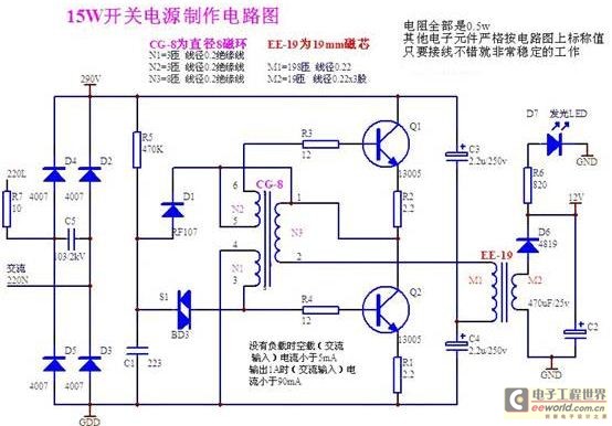
Structural analysis of switching power supply
A daily switching power supply primarily provides direct current (DC) power to electronic devices. The required DC voltage for electronic devices typically ranges from several volts to over ten volts, while the input voltage from the mains supply is either...
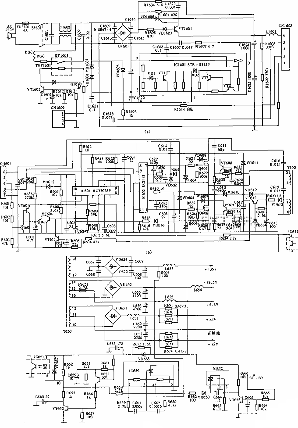
Sony KV-S29MHl TV switching power supply (SIR a 80145A) circuit diagram
The circuit of the Sony KV-S29MHl (S Movement series) TV switching power supply (SIR a 80145A) consists of three main sections: (A) the power oscillation part, (B) the regulator part, and (C) the output section.
The Sony KV-S29MHl TV switching power...
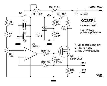
KC2ZPLs Web Design and Electronic Home
Now that these power supplies are available, it would be beneficial to evaluate their performance. Traditionally, an adjustable load (a robust resistor) is connected to the output to measure both output voltage and current at various points. This allows for...
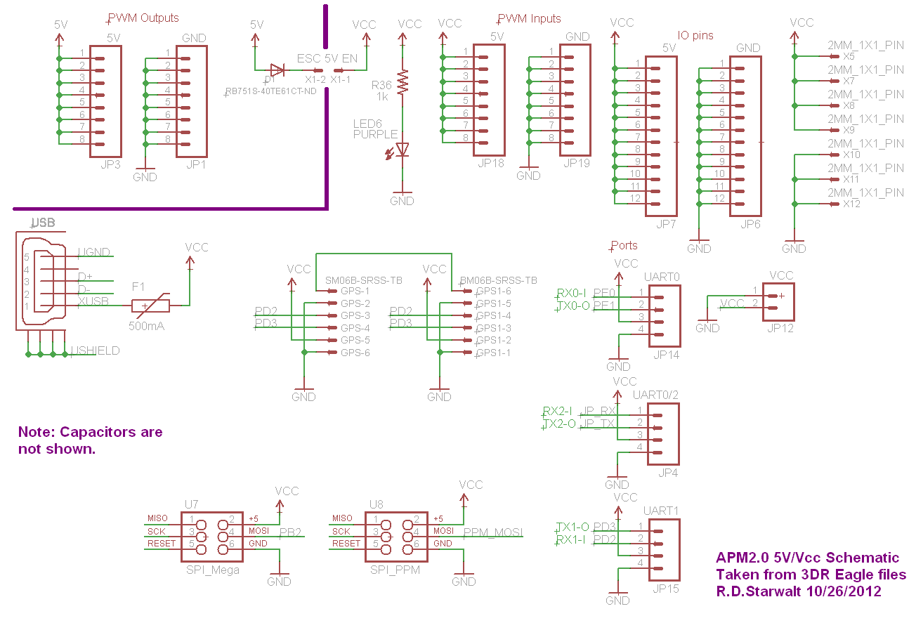
APM2.0 5V/Vcc Schematic
The PWM Output section has been separated into the upper left corner, delineated by a heavy purple line that is bridged by jumper JP1 on the APM2.0. This design choice highlights that diode D1 allows current to pass through JP1,...
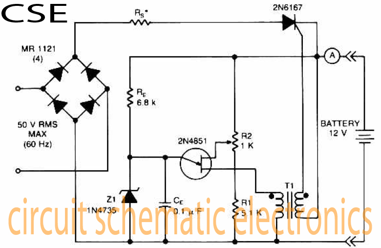
Variable charger circuit Schematic Diagram
The accumulator charger circuit must provide a voltage that matches the specifications of the batteries being charged. For a 12-volt accumulator, the output voltage should not exceed 12 volts, nor should it fall significantly below this threshold. Failure to maintain...
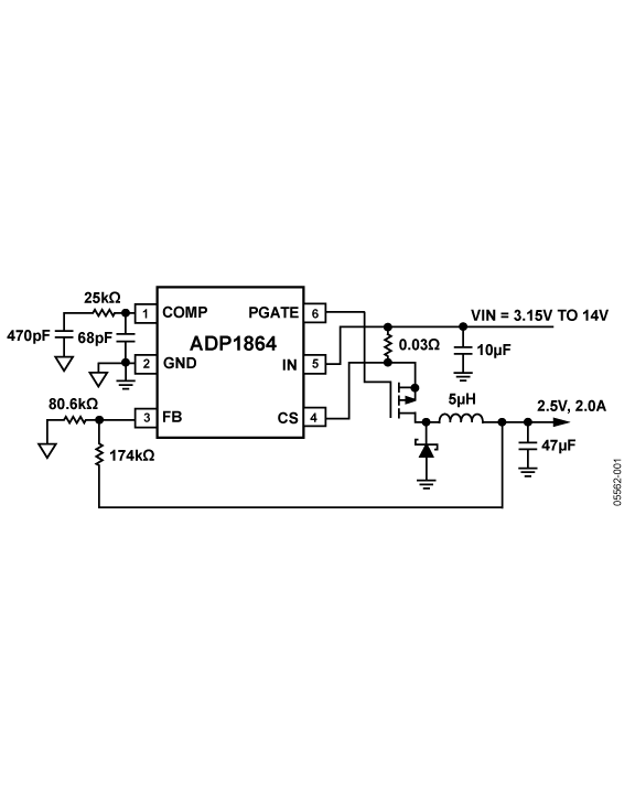
power switching controllers external switches
The ADP1864 is a compact, cost-effective, constant-frequency current-mode step-down DC-DC controller. It drives a P-channel MOSFET to regulate an output voltage as low as 0.8 V with ±2% accuracy, handling load currents up to 5 A from input voltages as...
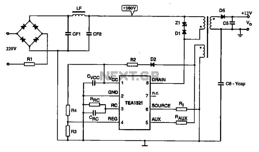
A typical DVD switching power supply circuit
A typical DVD switching power supply circuit is shown in the standby power supply circuit of digital products. It utilizes a switching power supply structure, with the oscillation switch IC EA1623 providing oscillation pulses to the transformer. The secondary output...
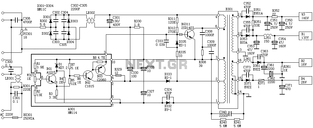
Sanyo 83P switching power supply circuit diagram
Oscillation: The positive terminal voltage of C310 is approximately 300V. The resistors R311 and R312 are connected to the switch BG311 at the B pole, while the B301 winding via the switching transformer (4) and (6) is connected to the...
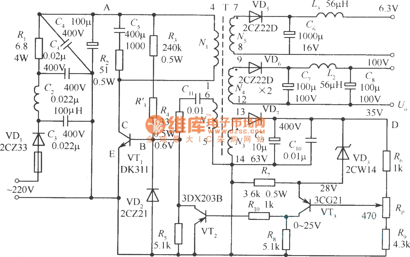
Output sampling winding isolated switching power supply
The diagram illustrates the output sampling winding of an isolated switching power supply. In the diagram, T represents a high-frequency transformer; N2 denotes the self-oscillation positive feedback winding; N3 is the error amplifier; VTS is the winding that provides the...