
Clap switch using timer 555


The described circuit functions as a clap-activated relay switch, which can be employed for various applications, such as controlling lights or other devices remotely. The primary components of the circuit include an electric microphone, an operational amplifier (op-amp), a 555 timer IC, a D-type flip-flop, and a relay.
The electric microphone serves as the input sensor, detecting sound waves generated by a hand clap. The output from the microphone is coupled through capacitor C1, which blocks any DC component and allows only the AC signal (the sound) to pass through to the op-amp (IC1). The op-amp amplifies the signal from the microphone to a level suitable for triggering the subsequent components in the circuit.
The amplified signal from IC1 is fed into the 555 timer (IC2), which is configured in monostable mode. In this configuration, the 555 timer generates a single output pulse in response to a trigger input. The duration of this pulse is determined by the resistor-capacitor (RC) time constant set by external components connected to IC2. This pulse is then used to trigger the D-type flip-flop (IC3).
The D-type flip-flop serves as a memory element, maintaining its output state based on the clock pulses it receives. In this circuit, the flip-flop is arranged in a three-state counter configuration, requiring two distinct trigger pulses (from two claps) to change its output state. When IC3 receives the second pulse, it sets its output high, activating the transistor Q1, which in turn energizes the relay K1. This relay can control any connected device by closing or opening its switch contacts.
To turn off the device, the circuit requires an additional two claps. This design ensures that accidental noise does not inadvertently trigger the relay. The sensitivity of the circuit is adjustable through resistor R3, allowing the user to fine-tune the system to ignore ambient noise levels while still responding to the intended clap sound.
Overall, this circuit provides a practical solution for hands-free control of electrical devices, making it particularly useful for applications where manual operation is inconvenient.A single hand clap will be picked up by the electric mic which is coupled through C1 into the op amp IC1. The output of IC1 triggers the 555 IC timer IC2 which is configured as a monostable multivibrater. The trigger pulse is stretched by IC2 and outputs a pulse to IC3 a D type flip flop. Because of the three state counter arrangement of IC3, two sharp claps are required before IC3 will output a high to Q1 which will turn on K1 relay and any device connected to K1's switch contacts.
Two more claps will clock IC3 again and will turn off Q1 and any device connected to the K1's contacts. I had my unit connected to my xmas tree lights so that I wouldn't have to crawl behind the tree to turn the lights on and off.
Sensitivity for the circuit is R3 and should be adjusted so that the circuit ignores normal room noise. 🔗 External reference
Related Circuits

The A/B switch circuit comprises three integrated circuits (ICs) and several resistors. Two gates from a 4011 quad 2-input NAND gate (U1A and U1B) are configured as a monostable multivibrator. When switch SI is activated, it triggers a 4017...

An AC-DC power supply without a power switching circuit is typically employed in lighting load circuits. When the power grid is restored, the standby power supply automatically switches on. The automatic switching circuit utilizes a transistor, as illustrated. The...
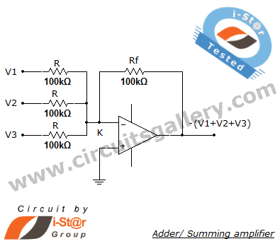
A summing amplifier, also known as an adder, is utilized to combine two or more signal voltages. This voltage adder circuit is straightforward and allows for the addition of multiple signals. It has a wide range of applications in...

Designing a wide-range variable power supply using a linear regulator is straightforward; however, it suffers from poor efficiency when regulating a constant 60-volt source. A wide-range variable power supply can be implemented using a linear regulator, which allows for adjustable...

By mixing an audio signal with ultrasound, it is possible to perceive the audio as if it originates from within the head, even when the 'headphones' are positioned far from the ears. Patrick Flanagan invented the "Neurophone" over 40...
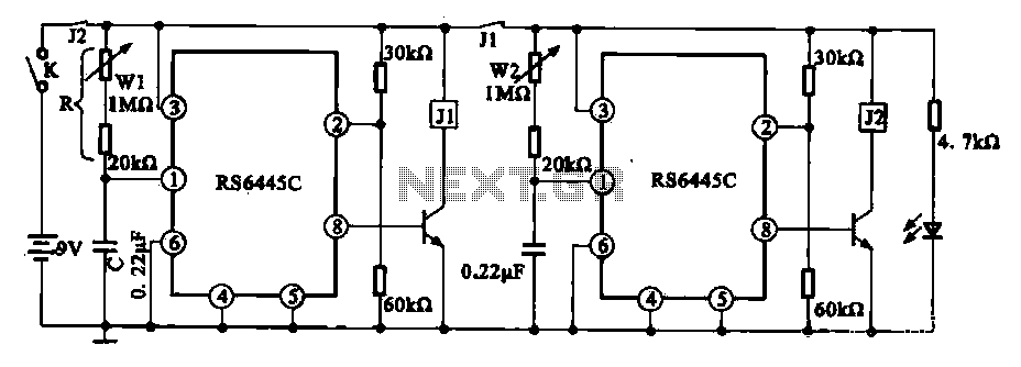
The timing integrated circuit (IC) RS6445C functions as a blocking oscillator. It features two segments, WI and W2, which are utilized to adjust the working time and the closure time. These adjustments can be continuously set within a range...