
Summing amplifier/ Inverting adder circuit using op amp 741
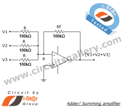
A summing amplifier circuit typically employs operational amplifiers (op-amps) configured to perform arithmetic addition of input voltages. The most common configuration is the inverting summing amplifier, where multiple input signals are fed into the inverting terminal of the op-amp through resistors. The non-inverting terminal is connected to ground. The output voltage is a weighted sum of the input voltages, with each input signal scaled by its corresponding resistor value. The relationship between the input voltages (V1, V2,..., Vn) and the output voltage (Vout) can be expressed by the formula:
Vout = - (R_f / R1 * V1 + R_f / R2 * V2 + ... + R_f / Rn * Vn)
where R_f is the feedback resistor and R1, R2, ..., Rn are the resistors connected to the inputs.
This configuration allows for flexibility in signal processing, making it suitable for applications such as audio mixing, where signals from various sources need to be combined while maintaining control over individual signal levels. The ability to adjust the gain for each input independently is achieved by selecting appropriate resistor values.
In cases where non-inverted output is required, a non-inverting summing amplifier can be implemented. This can be done by using a second op-amp stage that follows the inverting summing amplifier. The second stage can be configured to provide the desired gain and phase characteristics, allowing for greater versatility in circuit design.
Overall, summing amplifiers are essential components in various electronic applications, providing a means to combine multiple signals effectively while maintaining control over the output characteristics.Summing amplifier or an adder is used to sum two signal voltages. Voltage adder circuit is a simple circuit that enables you to add several signals together. It has wide variety of applications in electronic circuits. For example, on a precision amplifier, you may need to add a small voltage to cancel the offset error of the op amp itself. An audi o mixer is another good example of adding waveforms (sounds) together from different channels (vocals, instruments) before sending the combined signal to a recorder. You can change the gain or add another input without messing up with the gains of other inputs. Just remember that the inverting summing amplifier circuit inverts the input signals. That`s not a big deal. If you need the opposite polarity, all you have to do is to put an inverting stage before or after the summer.
🔗 External reference
Related Circuits
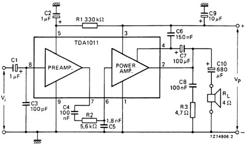
The following schematic illustrates the design of a 4 Watt Amplifier Circuit Diagram intended for portable radio applications, utilizing the TDA1011 integrated circuit from Philips Semiconductor. The 4 Watt Amplifier Circuit is designed to provide audio amplification in portable radio...
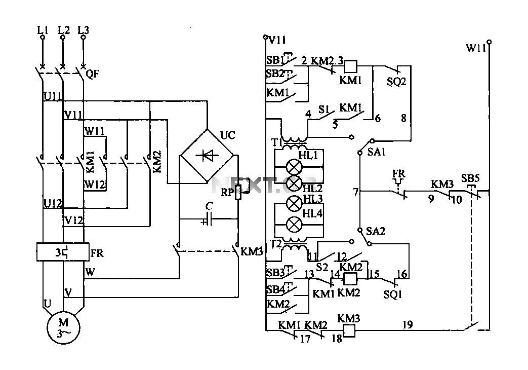
The electric valve control circuit consists of three main parts: the main lines, control lines, and power consumption brake line. The main circuit includes a power switch (QF), three-phase AC contactors (KM1, KM2), a thermal relay (FR), and a...
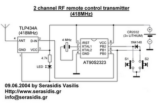
The following circuit illustrates a 3V power supply designed for an RF remote control circuit. This circuit is based on the AT90S2323 integrated circuit (IC). Features include a data rate of 2400 bps. The 3V power supply circuit for the...
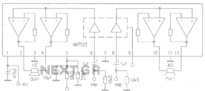
AN7522 is a Panasonic stereo audio amplifier IC that delivers an output power of 3W at 8 ohms. It features a standby function, low static power consumption, and reduced noise levels, requiring fewer external components for stable operation. This...
An ideal solution for making a good, low-cost power amplifier. It's an ideal solution for creating a home cinema system. The preamplifier and the driver are supported in an operational amplifier [IC1]. The voltage drop in resistors R5 and...

The DTMF decoder can be powered by a 9V battery or through a parallel printer port. It is capable of detecting and displaying all 16 DTMF digits on a computer screen in real-time. The accompanying Windows program can run...