
Class A Preamplifier Circuit
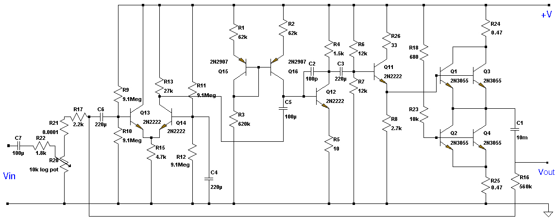
This Class A preamplifier circuit is designed to provide high fidelity signal amplification with minimal distortion. The symmetrical structure allows for balanced signal processing, which is essential in audio applications to maintain signal integrity. The use of dual transistors T1 and T2 in the input differential stage enhances the circuit's ability to reject common-mode signals, improving the overall noise performance.
Transistor T12 plays a critical role in ensuring polarization correction, which compensates for variations in transistor characteristics that can lead to unequal amplification. This correction is vital for maintaining linearity and stability across the operating range of the preamplifier. The adjustment of output voltage to zero via potentiometer P2 allows for fine-tuning of the circuit, ensuring that any DC offset is eliminated, which is particularly important when interfacing with subsequent audio stages.
The contact between the surfaces of transistors T7, T9, T8, and T10 is critical for thermal stability and performance consistency. Proper thermal management prevents thermal runaway, which can adversely affect the circuit's performance. The repose current adjustment for T9 and T10, set to 20mA with potentiometer P1, allows for precise control of the biasing conditions, further enhancing the linearity and efficiency of the amplification process.
With a frequency bandwidth of 2.4 MHz, this preamplifier is capable of handling a wide range of audio frequencies, making it suitable for various applications, including high-fidelity audio systems and professional audio equipment. The design emphasizes reliability and performance, ensuring that the preamplifier meets the demands of modern audio processing while maintaining high standards of sound quality.This class A preamplifier has been designed in a symmetrical structure. In the input differential stages we`ve used the dual transistors T1 and T2. Polarisation correction is essential because of the amplification differences and is assured with T12. P2 brings the output voltage to 0. For maximum performances, T7 and T9 surfaces must be in contact , also T8 and T10 surfaces. The T9 and T10 repose current is adjusted to 20mA with P1. Frequency bandwidth is 2. 4MHz. 🔗 External reference
Related Circuits
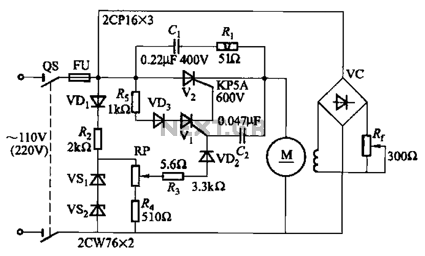
A 100W resistance-triggered motor control circuit designed for arc welding machines. It features an adjustment potentiometer (Rr) that can modify the DC motor excitation current. Additionally, a regulator (RP) is included to adjust the DC motor armature voltage, enabling...
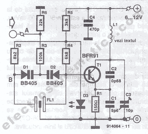
This UHF transmitter is designed for low power applications such as remote controls for garage doors, operating systems, and wireless alarms. This UHF FM transmitter is equipped with... This UHF transmitter operates within the Ultra High Frequency (UHF) band, which...
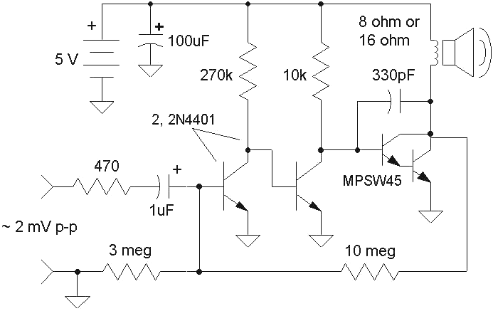
A Class-A audio amplifier is known for its high power consumption; however, its simplicity is appealing when ample power is available. This circuit features a Darlington transistor designed for use with a 5-volt power supply. It is important to...
This application note describes the evaluation board for the AD7892-2, a 12-bit analog-to-digital (A/D) converter. The AD7892-2 is a high-speed, low-power device capable of 500 ksps sampling rate, operating from a single +5V supply. It features an on-chip track/hold...
The FKL-32 type automatic thyristor excitation device is designed for synchronous generators with a terminal voltage of 400V and a capacity of 500kW and below. It is used for the automatic adjustment of excitation. The FKL-32 thyristor excitation device is...
The resistors were not measured precisely, and given their ±5% tolerance, along with a Vref range of 1.2 to 1.3 volts, it is possible to exceed 6 volts in certain scenarios. A discussion arose regarding the effectiveness of these...