
Standlight circuits
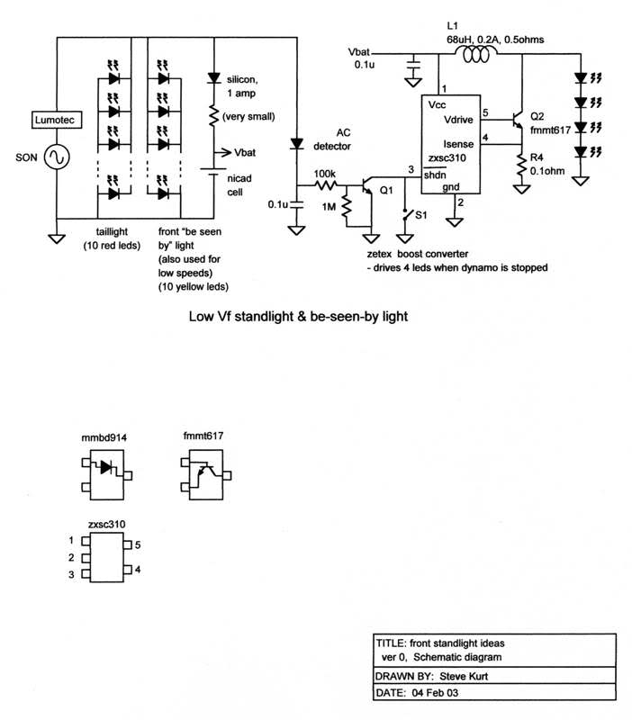
The circuit in question involves a light-emitting diode (LED) system powered by a dynamo, with a focus on optimizing the standlight functionality. The design incorporates resistors with a tolerance of ±5%, which can lead to voltage variations, particularly when interfacing with a reference voltage (Vref) that ranges from 1.2 to 1.3 volts. This variability necessitates careful consideration of the circuit's components and their tolerances to avoid exceeding voltage limits, which can adversely affect performance and reliability.
The use of supercapacitors in the design presents an opportunity for energy storage, facilitating the operation of the LED in standlight mode. The complexity of commercial circuits indicates that the performance enhancements achieved may justify the additional components. However, for a DIY approach, a simpler circuit design could yield satisfactory results with reduced complexity. The integration of a flashlight as a standlight alternative highlights a practical solution for providing illumination during repairs while maintaining a minimalist design.
In the experimental phase, various configurations are being tested, including the use of a clamped circuit and the arrangement of supercapacitors in series and parallel. The latter configuration is particularly noteworthy, as it can effectively double the energy storage capacity while ensuring the circuit remains within safe operational limits. The suggestion to use two 5.5V capacitors in series underscores the importance of understanding the relationship between voltage, capacitance, and LED forward voltage drop (Vf), which is critical for maintaining the intended functionality of the light system.
The iterative process of testing and refining the circuit design is essential for achieving optimal performance. Adjustments to resistor values based on measured diode drops can lead to more accurate voltage regulation and current flow, which are vital for the LED's operation. The updated circuit diagram, featuring the LM317L voltage regulator, serves as a visual aid for understanding the circuit's layout and functionality, while also providing cautionary notes regarding component tolerances and potential worst-case scenarios.
Overall, this project exemplifies the balance between complexity and performance in electronic circuit design, particularly in applications where reliability and efficiency are paramount.Didn`t measure my resisitors exactly and since they are +/-5% and Vref has a range of 1. 2 to 1. 3 volts you can easily end up over 6 volts. Here is a worst case example: The reason that I disagree with that statement is that they clearly work well in commercial headlights. The IQ Fly dims in standlight mode, but still puts out more light than the 30-50ma that works well for this circuit.
The reason that I disagree with that statement is that they clearly work well in commercial headlights. The IQ Fly dims in standlight mode, but still puts out more light than the 30-50ma that works well for this circuit.
I have a B&M d`Lumotec Oval N-plus, and I appreciate the quality of its standlight. I do think useful things can be done with supercaps. I`ve been told that the commercial standlight circuits are really complex, and presumably the designer felt that the performance improvement was worth accepting the additional complexity. Personally, if I were making a home-built standlight I would use something much simpler with a modest performance degradation.
With that said, I now use a self-built LED dynamo light with no built-in standlight. A flashlight, which I require anyway for repairs in the dark, sits on my bars and performs the standlight function. As I`ve mentioned before, I think this is the simplest solution of all. As always, your mileage may vary. I finally got the breadboard from a friend tried out the most basic circuit, and found the results underwhelming.
I`ll try out frontranger`s clamped circuit feeding off 7. 2v and report back. I`ll also try it with a second supercap in series instead of diode clamps and with the clamps but the 2nd supercap in parallel and see how it goes. edit: After talking it over with a friend, it seems that keeping the clamp but using the supercaps in parallel is the most reasonable thing to try if I`m only powering one LED.
I`m beginning to wonder if the best approach is to use 3 optics and LEDs. 2 would be used as driving lights and would be on when riding. The third would be used only as a standlight, run at reduced current, and have a wider beam angle. Assuming any of this stuff ever gets off the breadboard, I was thinking a triple LED setup with 2 narrow optics, and 1 oval optic. The oval optic would be backed by the supercap(s). I finally got the breadboard from a friend tried out the most basic circuit, and found the results underwhelming.
I`ll try out frontranger`s clamped circuit feeding off 7. 2v and report back. I`ll also try it with a second supercap in series instead of diode clamps and with the clamps but the 2nd supercap in parallel and see how it goes. edit: After talking it over with a friend, it seems that keeping the clamp but using the supercaps in parallel is the most reasonable thing to try if I`m only powering one LED.
Your friend is right. Two 5. 5V caps in series can easily tolerate 7. 2 V, but their effective capacitance is half of a single cap, and they can only discharge down to 2x nearly-off LED Vf. The second method will double the energy stored. Also, as I mentioned earlier, the resistor value was approximate, because the diode drops were approximated.
You can either play with the resistor value, or measure the diodes drops and calculate. If you have a solderless breadboard and a nice complement of resistors, I bet the former is faster. I updated the original diagram with the LM317L circuit on flickr and replaced with a diagram with a warning about tolerances and the worse case possibility. I`ve updated the link in my original message here, but other messages (such as Alex`s) will have broken images.
I also built up 🔗 External reference
Related Circuits
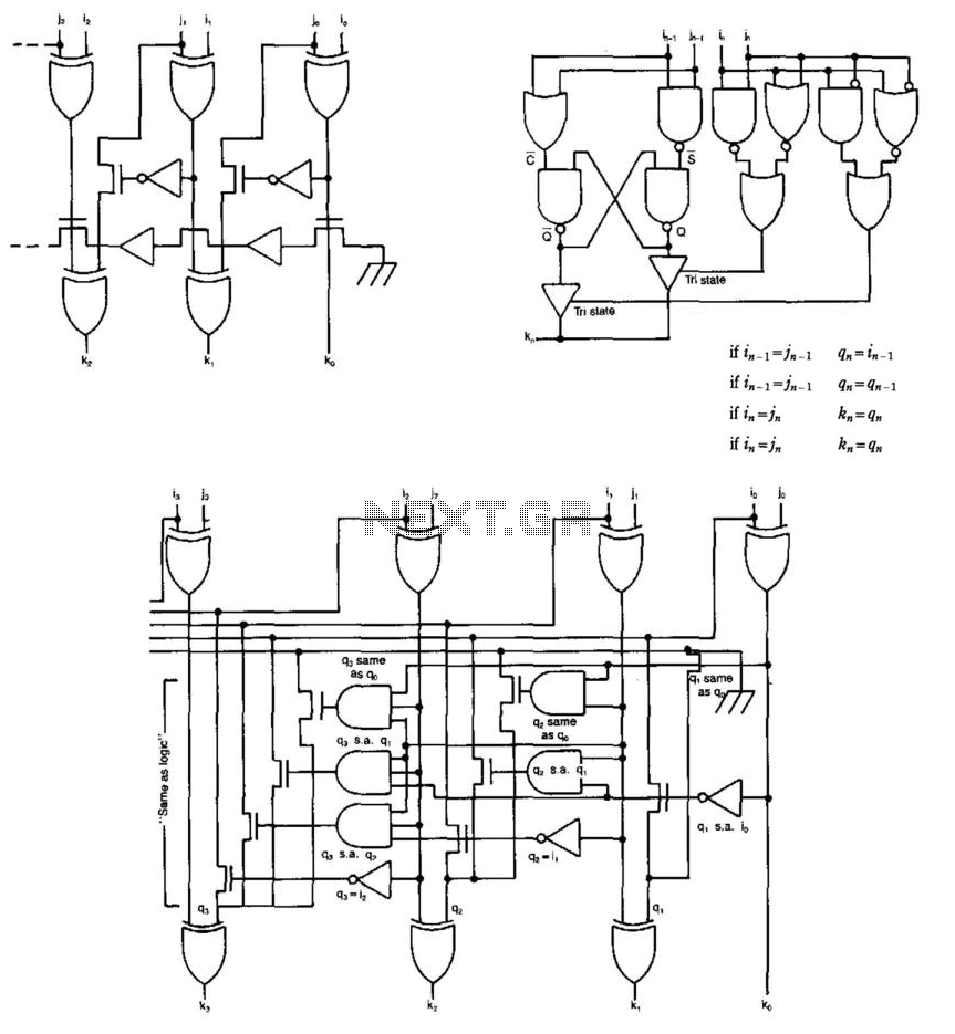
Some circuits that add binary numbers experience time delays due to carry propagation. This issue has been partially addressed by the carry look-ahead adder. However, the complexity of this method typically limits its application to no more than 4...
An advantage of a photogate over a sound trigger is that the former activates based on the exact position of the object that interrupts the beam. For instance, the shape of a snapped elastic cord can be captured as...
To prevent soldering errors, students were instructed to place all their resistors on the board first. Once their placements were verified, they could proceed with soldering. Capacitors were next, followed by LEDs and other components. The middle school class...
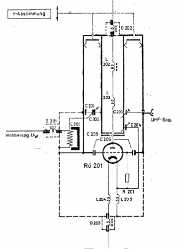
The use of a quarter-wave parallel-wire line as a tuning unit has been discussed in the chapter on Short Lines, where it was pointed out that these circuits have comparatively high Q even at higher frequencies. Their great length...
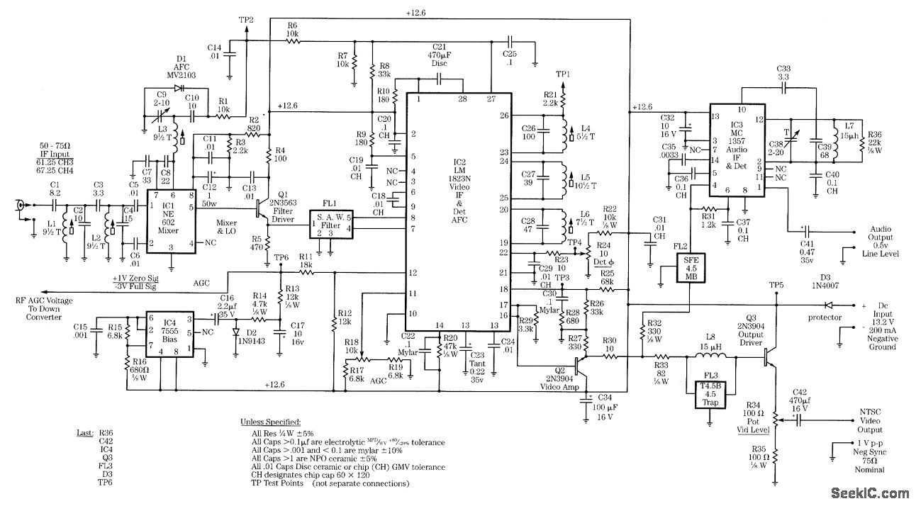
Radio-frequency schematics (also see NE602 datasheet and application note). This page contains electronic circuits related to RF receivers. This index features a broad collection of RF receiver circuits. Radio-frequency (RF) schematics are essential for designing and implementing circuits that operate...
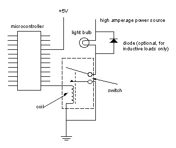
Digital output from a microcontroller is typically a low-amperage signal. For example, when a pin is set HIGH on the microcontroller (in Wiring/Arduino, it is digitalWrite(somePin, HIGH);), the voltage from that pin is usually +3.3V or +5V, with the...