
CMOS Pocketable Timekeeper

The CMOS Pocketable Timekeeper circuit utilizes complementary metal-oxide-semiconductor (CMOS) technology, which is known for its low power consumption and high noise immunity. The design typically includes a crystal oscillator to provide a stable clock signal, which is essential for accurate timekeeping. The oscillator's frequency is usually set to 32.768 kHz, a standard frequency for timekeeping applications, allowing the circuit to maintain precise time over extended periods.
The circuit may incorporate a microcontroller or a dedicated timer IC, which processes the clock signal and manages timekeeping functions. This component is responsible for counting the clock pulses and converting them into human-readable time formats, such as hours, minutes, and seconds. Additionally, the microcontroller may include features like an alarm function, timer settings, and user interface controls, such as buttons for adjusting the time.
Power management is a critical aspect of the design, especially for a pocket-sized device. The circuit typically operates on a low-voltage power supply, often using a coin-cell battery. This design choice enhances portability while ensuring that the device can function for extended periods without frequent battery replacements.
The output of the timekeeping circuit can be displayed on a small LCD or LED screen, showcasing the time in a clear and readable format. The schematic may also include additional components such as resistors, capacitors, and diodes to filter noise and stabilize the power supply, ensuring reliable operation of the timekeeping function.
In summary, the CMOS Pocketable Timekeeper circuit diagram represents a sophisticated yet compact design that effectively combines various electronic components to create an efficient and portable timekeeping solution suitable for a wide range of applications.CMOS Pocketable Timekeeper is pocket size time circuit circuit diagram of CMOS Pocketable Timekeeper and various other timer project advanced timer and electronics project. 🔗 External reference
Related Circuits
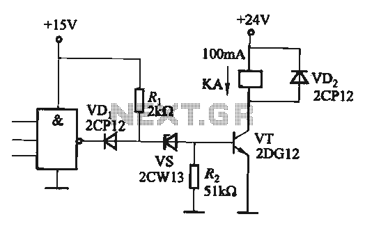
If the CMOS circuit load (actuator) is a relay device, the circuit must have a large load capacity. Non-gate drive switching amplifiers are connected to a separate element shown in the interface circuit. In the context of a CMOS circuit...
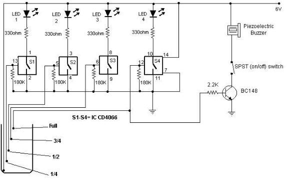
A simple and cost-effective water level indicator circuit can be designed using this schematic. This water level indicator utilizes a CMOS IC CD4066 to indicate the amount of water present in an overhead tank and to provide an alarm...
The following circuit illustrates a 5 Zone Anti-Theft Circuit Diagram. This circuit is based on the CMOS 4050B IC. Features: the system may comprise in... The 5 Zone Anti-Theft Circuit utilizes the CMOS 4050B integrated circuit, which is a hex...
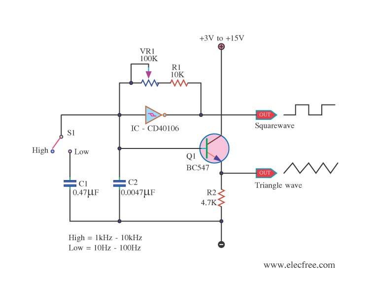
This is a function generator project that can be used as a triangle and square wave generator. The main components include the CD40106, a popular CMOS integrated circuit, and a standard transistor. The function generator circuit utilizes the CD40106, which...
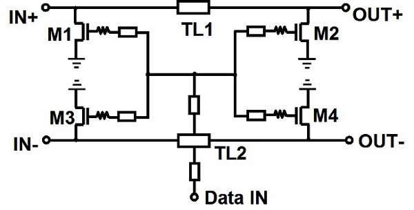
An edge combiner utilizing MOSFETs C and D is designed to generate a 16 ps pulse. The center frequency varies as a function of the NMOS width (Wser) relative to the inverter width (Winv). Figure 12 illustrates the transmitted,...
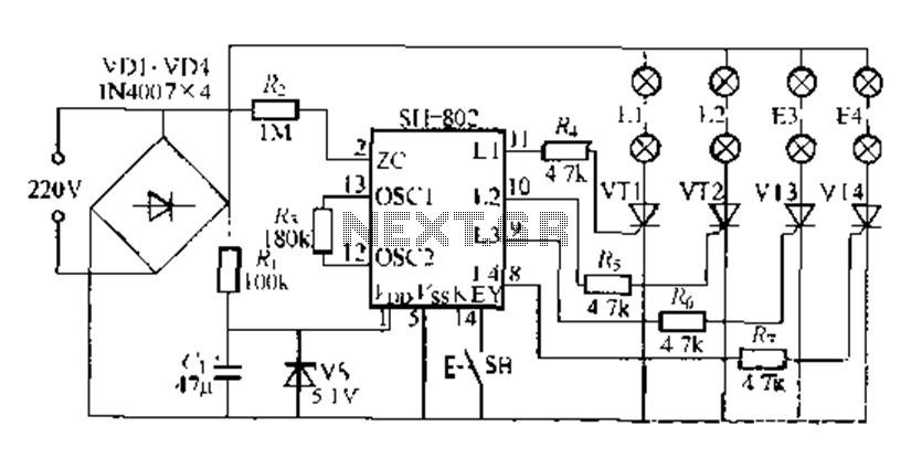
A digital integrated circuit simplifies the response process significantly. The diagram illustrates a circuit comprising four responder groups. The digital integrated circuit described serves as a crucial component in various electronic systems, primarily focusing on enhancing response efficiency. It comprises...