
coilless FM transmitter circuit diagram
The described RF oscillator circuit is designed to generate a modulated RF signal suitable for FM transmission. The core of the circuit is the inverter N2, which serves as the oscillator, working in conjunction with a 10.7 MHz ceramic filter to stabilize the frequency. The output from inverter N2 is fed into a series of inverters (N4 to N6) connected in parallel, which effectively lowers the output impedance, allowing for efficient power transfer to the antenna. The choice of a 1/4 wavelength aerial is critical, as it ensures optimal radiation of the RF signal.
The square wave output from the inverters introduces harmonics due to its non-sinusoidal nature. The 9th harmonic, calculated at 96.3 MHz, is particularly significant as it aligns with the FM broadcast band, making this oscillator suitable for FM transmission applications.
Inverter N1 plays a pivotal role as an audio amplifier, taking input from an audio source such as a microphone. The amplified audio signal is then directed to a varicap diode, which is a voltage-variable capacitor. The capacitance of the varicap changes in response to the audio signal, which in turn alters the frequency of the oscillator. This process is essential for achieving frequency modulation, where the frequency of the RF carrier signal varies in accordance with the amplitude of the audio input.
The circuit's design allows for effective modulation of the RF signal, making it applicable for various communication systems. Careful consideration should be given to the layout and component selection to minimize interference and ensure reliable operation. The circuit's performance can be further enhanced by implementing filtering techniques to reduce unwanted harmonics and improve signal clarity.The RF oscillator using the inverter N2 and 10. 7Mhz ceramic filter is driving the parallel combination of N4 to N6 through N3. Since these inverters are in parallel the output impedance will be low so that it can directly drive an aerial of 1/4th wavelength. Since the output of N4-N6 is square wave there will be a lot of harmonics in it. The 9th ha rmonics of 10. 7Mhz (96. 3Mhz) will hence be at the center of the FM band. N1 is working as an audio amplifier. The audio signals from the microphone are amplified and fed to the varycap diode. The signal varies the capacitance of the varycap and hence varies the oscillator frequency which produce Frequency Modulation. Disclaimer: All the information present on this site are for personal use only. No commercial use is permitted without the prior permission from authors of this website. All content on this site is provided as is and without any guarantee on any kind, implied or otherwise.
We cannot be held responsible for any errors, omissions, or damages arising out of use of information available on this web site. The content in this site may contain COPYRIGHTED information and should not be reproduced in any way without prior permission from the authors.
🔗 External reference
Related Circuits
1 kHz RC phase shift oscillator circuit The 1 kHz RC phase shift oscillator circuit is designed to generate a continuous sine wave output at a frequency of 1 kHz. This circuit typically utilizes a combination of resistors and capacitors...
This automatic NiCd charger for 9V NiCd batteries utilizes the properties of a 555 timer and is straightforward to construct. The charger is designed to automatically maintain a full charge on the battery, allowing it to remain connected for...
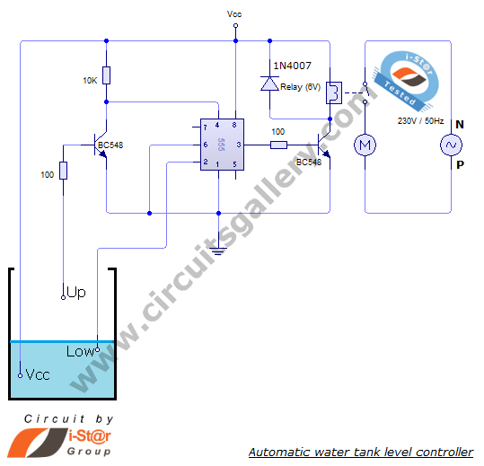
The automatic water level controller circuit is a straightforward engineering project that can automatically switch a domestic water pump on and off based on the water level in a tank. This motor driver circuit can be implemented at home...

The Dodge Aspen was a compact car produced from 1976 to 1980 by Chrysler Corporation's Dodge division. The 1976 Aspen model year was available as a 2-door coupe, 4-door sedan, or 4-door station wagon, and it came in three...
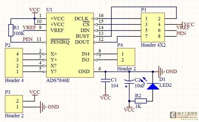
The touch control screen is a common feature in modern electronic products, typically incorporating a colored liquid crystal display (LCD) with a touch-sensitive interface. This technology is user-friendly and effectively replaces traditional fixed keypads. This document introduces the driving...
4V flat monitor high voltage power supply circuit diagram. A wide range of 7 to 40V to 5V DC-DC step-down circuit diagram. Light control switch circuit diagram for safety. Circuit 555 constitutes a control circuit diagram for photoelectric applications. The...