
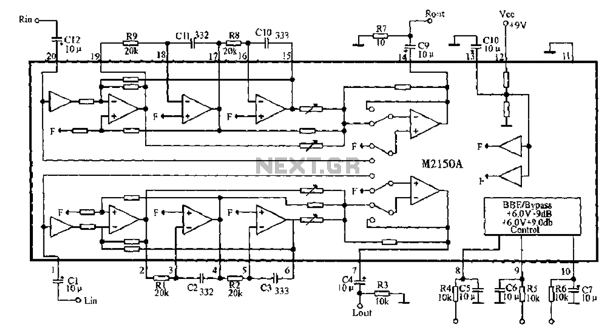
BBE monolithic integrated circuit M2150A
The 4V flat monitor high voltage power supply circuit is designed to provide a stable and efficient voltage source for flat panel displays. This circuit typically includes components such as a transformer, rectifier, and voltage regulator to convert high voltage input into a usable 4V output. The design ensures that the monitor operates within its specified voltage range, preventing damage from over-voltage conditions.
The DC-DC step-down circuit, which can accept an input voltage range of 7V to 40V and output a regulated 5V, employs a buck converter topology. This circuit utilizes an inductor, a switch (typically a MOSFET), and a diode to efficiently convert the higher input voltage to a lower output voltage while minimizing power loss. The switching frequency and duty cycle are critical parameters that must be optimized to achieve high efficiency and low ripple in the output voltage.
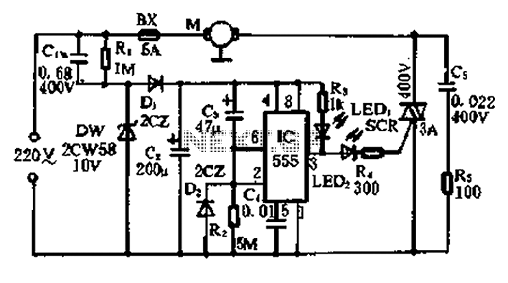
The light control switch circuit diagram emphasizes safety by integrating features such as overload protection and short-circuit prevention. This circuit may include a relay or a solid-state switch that controls the light load based on input signals, ensuring that the lighting system operates safely under varying conditions.
The 555 timer circuit is a versatile component often used in control applications, including photoelectric systems. In this configuration, the 555 timer can be set up in either monostable or astable mode to create timing pulses or oscillations that control other components in the system. This allows for precise control of devices based on light detection, enhancing the overall functionality of the circuit.
These circuits are integral to modern electronic applications, providing reliable power management and control solutions across various devices and systems.4V flat monitor high voltage power supply circuit diagram innocentA wide range of 7 ~ 40V turn 5VDC-DC step-down circuit diagramLight control switch circuit diagram of a safety circuit555 constitute a control circuit diagram of a photoelectric
Related Circuits

This circuit utilizes a single potentiometer to control a frequency range from 300 Hz to 3000 Hz. A FET operational amplifier is employed at stages A1 and A2. The upper frequency limit is dictated by the gain-bandwidth product of...
A 5-minute circuit can continue to operate during a power outage, providing protection for the refrigerator. The refrigerator power protection circuit, designated as 1136, includes a power transformer that converts 220V voltage through a rectifier bridge (VD1). This setup...
The circuit utilizes a transistor to amplify the input signal. Two diodes are employed to clamp the distorted output, while a 500 pF capacitor filters out high-frequency noise. Under normal conditions, a 1M slide rheostat is used to adjust...
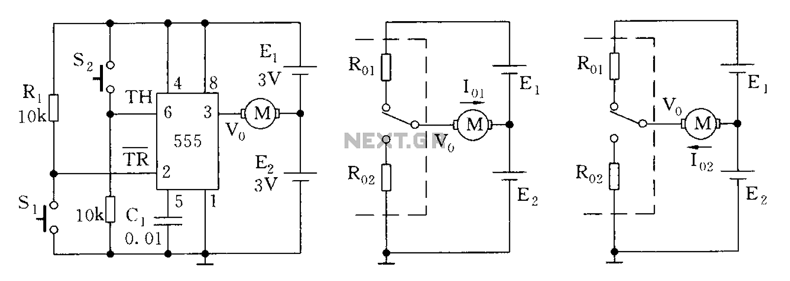
The 555 timer in bistable mode has fewer applications compared to its stable and monostable modes. Bistable mode refers to the circuit configuration based on the R-S (Reset-Set) trigger mode. An example of this is a micro-motor reversing control...
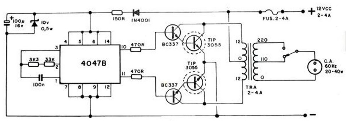
The converter transforms 12 VDC to 220 VAC, allowing for the conversion of 12 volts DC into 220 volts AC. The circuit diagram provided illustrates a simple converter circuit. This DC to AC converter can supply voltage for a...
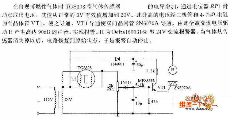
In the presence of combustible gas, the conductance of the TGS308 gas sensor increases, causing the voltage at the potentiometer RP1 slide point to rise from a normal 3V RMS to 20V. This elevated voltage is applied to transistor...