
Color Organ schematic

The project involves a sound-activated lighting system that utilizes an SCR (Silicon Controlled Rectifier) to control multiple light bulbs based on audio frequency input. The circuit is designed to connect directly to the output of a stereo system, allowing it to respond dynamically to the music being played.
The input audio signal is fed into a transformer that serves two purposes: it isolates the circuit from the high voltage present in the mains supply and helps to convert the audio signal to a level suitable for processing. The volume of the audio signal can be adjusted using a 5k ohm potentiometer, which allows for fine-tuning of the input level to prevent distortion or damage to the circuit components.
Within the circuit, a combination of resistors (R1, R2, R3) and capacitors is used to create a frequency-sensitive gate circuit. Each resistor-capacitor (RC) pair is tuned to respond to a specific frequency range of the audio signal. When the audio frequency matches the tuning of the RC circuit, it triggers the SCR, allowing current to flow to the corresponding light bulb. This results in the bulb illuminating in response to the specific frequency of sound, creating a visually engaging display that synchronizes with the music.
The choice of resistors in the circuit is crucial, as altering their values will change the frequency response of the gate circuit. This provides flexibility in the design, enabling customization based on the desired lighting effects and the characteristics of the audio being played.
The isolation transformer is a critical safety feature, ensuring that the low-voltage control circuit operates independently from the high-voltage mains supply while still being able to respond to the audio signals. This setup not only enhances safety but also improves the performance of the circuit by minimizing noise and potential interference from the power line.
Overall, this project combines audio signal processing and power control to create an interactive lighting experience, demonstrating the integration of electronics in entertainment applications. The basic idea of the project is to make different colored bulbs light at different frequencies of music. The circuit connects to the speaker outputs of your stereo or to the back of your speaker. The music passes through the transformer and the volume level is adjusted by the 5k ohm pot. Each light bulb is turn on by a different frequency of sound based on the resistor & capacitor combination in the gate circuit of the SCR.
If the resistors R1, R2, or R3 are changed, the frequency of sound that will trigger the SCR will change. The isolation transformer is for protection. 🔗 External reference
Related Circuits
This chapter provides detailed schematics of various power supplies suitable for use with common Ar/Kr ion tubes available to hobbyists in the surplus market. Included are examples of commercial designs (Omnichrome 150R and 532 head, Lexel 88 and head)...
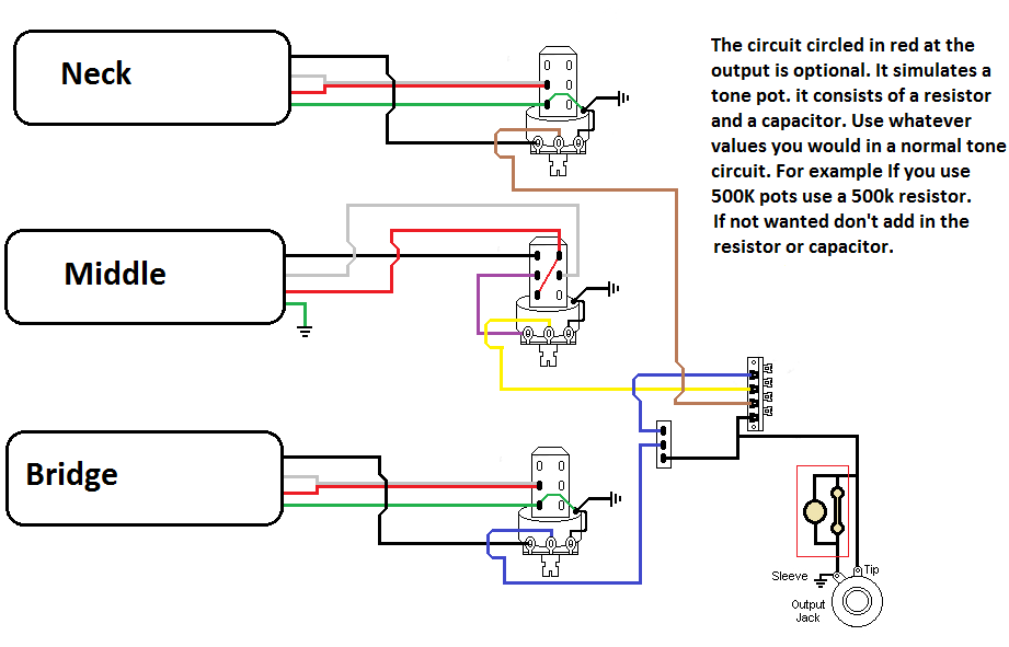
The pickups are connected to individual volume controls that feature push/pull functionality for coil tapping. They are routed to a 5-way switch before reaching the output jack. Additionally, a switch is desired to control the bridge pickup's activation when...
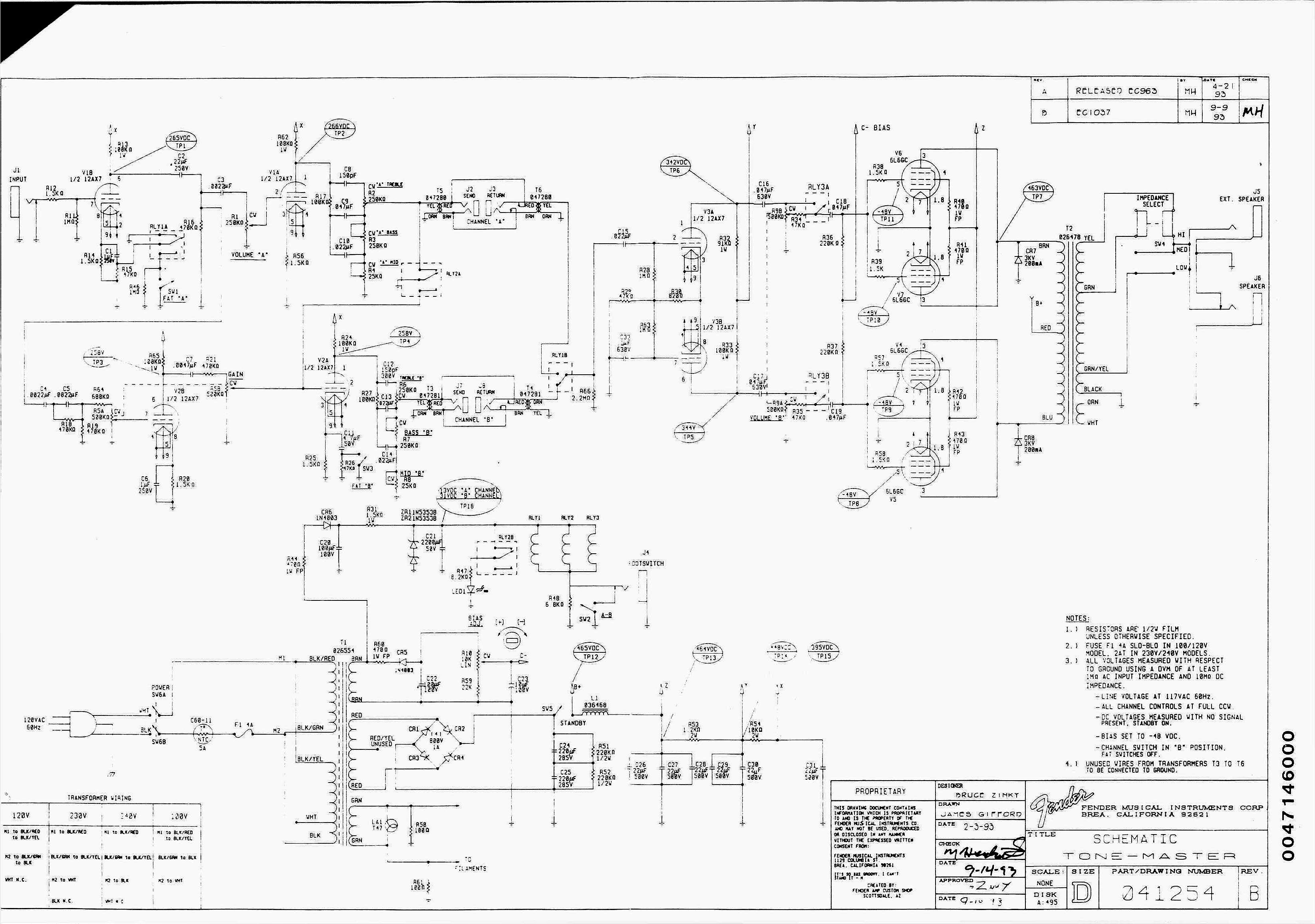
The schematics on this page are provided strictly for educational purposes. If anyone intends to use these designs for profit, they are required by law to obtain permission from the legal owner(s) of the design and comply with any...
The circuit consists of two main components: (1) a power supply circuit featuring a transformer (T) that steps down AC 220V to 33V, followed by a full-wave rectifier, a filter, and a three-terminal regulator that outputs +24V. This circuit...

This concept is somewhat different; however, a very simple method has been employed. Many people around the world search for UFOs by observing the sky, and often, wealthy individuals purchase expensive cameras to focus on the sky. In this...
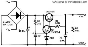
This circuit can be utilized in applications requiring high current and low ripple voltage, such as in high-powered Class AB amplifiers where high-quality audio reproduction is essential. Q1 and Q2, along with resistor R2, function as a power Darlington...