
Interesting Wiring Schematic
The circuit design incorporates a series of components aimed at enhancing the functionality and versatility of a guitar's pickup configuration. Each pickup is connected to an independent volume control, utilizing push/pull pots that allow for coil-splitting capabilities. This enables the player to switch between humbucking and single-coil sounds, providing a broader range of tonal options. The 5-way switch facilitates standard Stratocaster pickup selection, which includes the ability to combine pickups in various configurations for unique sound profiles.
To further augment the design, a secondary switch is integrated to control the bridge pickup's presence when the 5-way switch is in positions 1, 2, or 3. This feature allows for more nuanced control over the tonal palette, particularly beneficial for players who seek to maintain a specific sound profile without the bridge pickup interfering in certain selections.
The master volume control serves as the primary means of adjusting overall output, while the neck tone and neck/bridge tone controls allow for fine-tuning of the tonal characteristics. The push/pull functionality of these tone controls adds versatility, enabling phase switching or bypass options that can significantly alter the guitar's sound.
The wiring layout is crucial for achieving the desired independent or dependent volume scenarios. When configured for independent volumes, rolling off one pickup's volume will not affect the overall output, allowing for more dynamic playability. The proposed wiring also ensures that the Duckbucker pickup, which is not RWRP, is split to its south coil for hum cancelation, while the other pickups utilize their north coils.
The choice of pickups is aimed at achieving a versatile tonal response, with individual height adjustments available for each string. This feature allows for precise balancing of output levels across the strings, ensuring clarity in clean tones while maintaining body and warmth during overdriven settings. The overall design reflects a thoughtful approach to modernizing a classic guitar setup, offering musicians a comprehensive tool for expression and creativity.Those pickups go to their own volume controls that are push/pull so I can coil tap them, and then onto a 5 way switch before going to the jack. To make it slightly more complex though, I`d like to put in a switch that determines whether the bridge is on or not when the 5 way is in a position other than positions 4/5.
Then get a super switch and do the Mike Richardson mod using Master Volume, neck Tone, neck/bridge Tone with all three push/pull. One for the wiring, one for a neck phase, one as a "lead" bypass switch. MojoMonster: Currently, I set and forget the tone control so I want to avoid having a tone control where possible - I can always solder a resistor in if I find I have too much high end. hermetico: Yes, my intention was to run the volume/coil tap in series with the pickups before going to the switch.
Please can you elaborate on the independent/dependant volume scenario I`ve got it in my head that the volume controls will affect the signal going to the switch. Which is what I`d like to do! So if I`ve read this correctly you want all 3 humbuckers to be individually splittable via p/p pots and each pickup will have its own volume control.
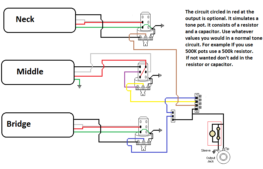
This will be standard strat switching with a another switch to add the bridge pickup to positions 1, 2, and 3 I did something along the same lines to an LP, I could draw you up a diagram later if you would like As promised here is a diagram for the switching options you wanted. I also included a small circuit on the diagram to simulate the very minor tonal effects of a tone pot turned up.
Even though you said you don`t use the tone control it still has an effect on the sound, albeit minor. I don`t believe the Duckbucker is RWRP, so the wiring I drew up splits the Duckbucker to the south coil as to provide hum-canceling.
The neck and bridge pickups split tot he north coil. If you have any questions I tend to check the board frequently. As promised here is a diagram or the switching options you wanted. I also included a small circuit on the diagram to simulate the very minor tonal effects of a tone pot turned up. Even though you said you don`t use the tone control it still has an effect on the sound, albeit minor.
I don`t believe the Duckbucker is RWRP, so the wiring I drew up splits the Duckbucker to the south coil as to provide hum-canceling. The neck and bridge pickups split tot he north coil. If you have any questions I tend to check the board frequently. good point hermetico. Some of this stuff has become second nature so I will occasionally overlook things like the ground to claw/bridge.
If you swap the leads on lugs 1 and 2 on the pot this should make the volume controls independent. If I have time when I get home from work I`ll update the diagram. On a completely unrelated note. Hermetic I was noticing your avatar and was wondering if were some kind of alchemist If so got any tips for turning lead to gold This diagram works with DEPENDENT volumes so, If you have two pickups selected in the 5-way switch and you completely roll off one of its pots, the entire axe will shut up. Does anyone have any comments regarding my choice of pickups I`m after a set that are really versatile (will do clean nicely, but don`t lose a round tone when they are used with OD etc).
I figured these were a good set to chose because of the individual height adjustment on the magnets per string which would allow me to tailor them to get a good balanced sound. 🔗 External reference
Related Circuits
The layout design of the TIQ Flash ADC closely follows the provided circuit diagram. A row layout is implemented, with rows stacked on top of each other. Each row comprises a comparator, a gain booster, a 0-1 generator, and...
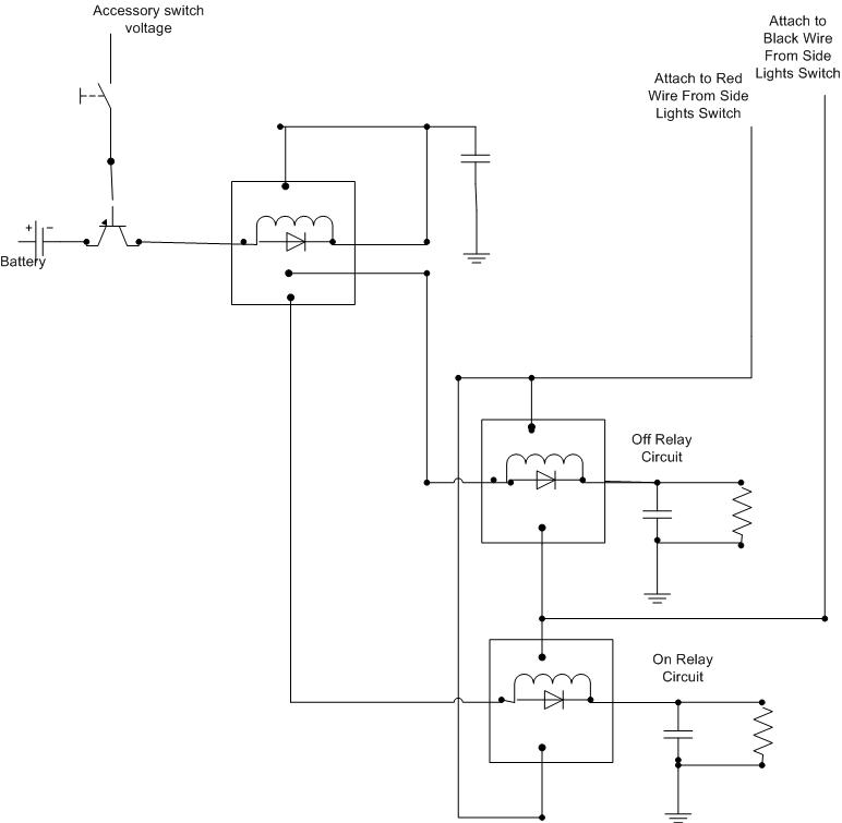
A decision has been made to install daytime driving lights for an Elise vehicle. The intention is to eliminate the need for manually pressing the button on and off repeatedly. The installation of daytime driving lights (DRLs) enhances vehicle visibility...
This infrared transmitter utilizes pulse width modulation (PWM). The transmitter is equipped with an LM567 tone decoder circuit. An audio signal (at least 50 mV peak-to-peak) is amplified with transistor T1 and subsequently used to modulate IC1. The frequency...
Instructions for constructing a circuit on veroboard by interpreting the schematic. Experienced constructors can directly reference the schematic to begin assembly, utilizing their knowledge of component placement and efficient use of veroboard space. Beginners should have certain foundational skills,...
Due to the high voltages present in the Charge and Primary sections, it is logical to seek cables with high voltage ratings, such as neon sign cables, medical X-ray equipment cables, and car engine spark plug leads. The first...
A bandpass filter passes a range of frequencies while rejecting frequencies outside the upper and lower limits of the passband. The range of frequencies to be passed is called the passband and extends from a point below the center...