
Color sensor amplifier circuit

The semiconductor color sensor operates by utilizing three photodiodes, each equipped with a specific color filter to detect the primary colors of light. The photodiodes PD1, PD2, and PD3 are responsible for capturing light reflected from an object, enabling the sensor to identify its color. The filters, labeled X-PHOTO, Y-PHOTO, and Z-PHOTO, correspond to the red, green, and blue wavelengths, respectively.
When light reflects off an object, it passes through the filters and reaches the photodiodes. Each photodiode generates a current proportional to the intensity of the light filtered through it. The output from each photodiode is a voltage signal that corresponds to the intensity of the red, green, or blue light detected.
These signals are then sent to operational amplifiers, which amplify the weak signals to a more usable level. The amplified signals are processed by a logic circuit that interprets the color data. The logic circuit analyzes the combination of amplified signals to determine the overall color of the object.
The amplification circuit, as depicted in Figure 7-23, includes configurations for the X, Y, and Z outputs, allowing for the effective representation of the color data. This circuit is instrumental in applications requiring color detection and analysis, such as in automated sorting systems, color matching in manufacturing processes, and advanced imaging systems that rely on accurate color representation. The reliability and precision of the semiconductor color sensor make it a valuable component in various technological applications where color identification is critical.Semiconductor color sensor having an identification of the object color capacity by three photodiodes PD1, PD2, PD3 and three color filters X-PHOTO, Y-PHOTO and Z-PHOTO constitution. Respectively mounted on each of the photo diode red (R), green (G), blue (B) color filters, from the reflected object light decomposed into three colors. After the color signal op amps after enlarging processing, processing logic depending on the combination of the color obtained after the actual output. Figure 7-23 is a color sensor s amplification circuit, the X, Y, Z output colors. The practical application of color vision based on the circuit.
Related Circuits
The circuit employs a widely used Sharp IR module (the Vishay module may also be utilized). The pin numbers indicated in the circuit pertain to both the Sharp and Vishay modules. For other modules, it is recommended to consult...

Automatic electronic refrigerator deodorant sterilization circuit The automatic electronic refrigerator deodorant sterilization circuit is designed to eliminate odors and sterilize the interior of a refrigerator. This circuit typically employs a combination of sensors, microcontrollers, and sterilization techniques to achieve effective...
A crystal oscillator circuit is a straightforward oscillator circuit that can be easily understood through its schematic diagram. It serves as a replacement for a conventional oscillator network, which typically consists of an LC combination. This simplicity is also...
A schematic diagram of a micropower single-supply instrumentation amplifier circuit is presented. This circuit requires only 15µA of current and can provide over... The micropower single-supply instrumentation amplifier circuit is designed for applications where low power consumption is critical. The amplifier...
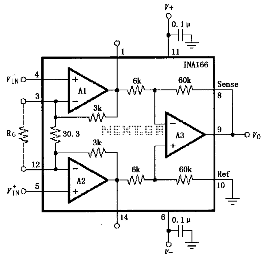
The basic connection circuit for the INA166 includes signal and power connections. A 0.1 µF tantalum capacitor should be used for filtering the chip's power supply terminal, and the PCB layout should be designed to position this capacitor as...
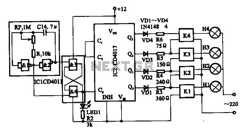
This circuit illustrates a circular lighting control system. It consists of four two-input NAND gates from the CD4011 series, which form a non-inverting multivibrator. This multivibrator generates a pulse that is used to shape the output of an RS...