
Micropower Single-Supply Instrumentation Amplifier

The micropower single-supply instrumentation amplifier circuit is designed for applications where low power consumption is critical. The amplifier operates with a supply voltage typically ranging from 1.8V to 5V, making it suitable for battery-operated devices.
The core of the circuit typically includes three operational amplifiers (op-amps) configured to provide high input impedance, excellent common-mode rejection ratio (CMRR), and differential signal amplification. The first two op-amps serve as input stages, allowing the circuit to amplify the difference between two input signals while rejecting any common-mode signals. The third op-amp is used for further amplification and to set the gain of the circuit, which is adjustable through external resistors.
To achieve such low power consumption, the op-amps used in this circuit are specifically designed for micropower applications. They feature low bias currents and low offset voltages, which are crucial for maintaining accuracy in low-power scenarios. The circuit also employs techniques such as biasing and feedback to minimize power usage while maintaining performance.
The output of the instrumentation amplifier provides a differential signal that can be fed into an analog-to-digital converter (ADC) or further processing stages. The low current requirement of 15µA allows this circuit to be integrated into portable devices, sensor applications, and other low-power systems where efficiency is paramount.
In summary, this micropower single-supply instrumentation amplifier circuit is an effective solution for low-power applications, providing high accuracy and performance while consuming minimal current.A schematic diagram of a micropower single-supply instrumentation amplifier circuit is shown below. This circuit only need 15µA of current and can give over.. 🔗 External reference
Related Circuits

This is a linear amplifier that requires advanced knowledge in electronics due to the complexity of the schematic diagram for a handmade circuit. It is advisable to redesign the schematic diagram using circuit design software such as DipTrace, Eagle,...
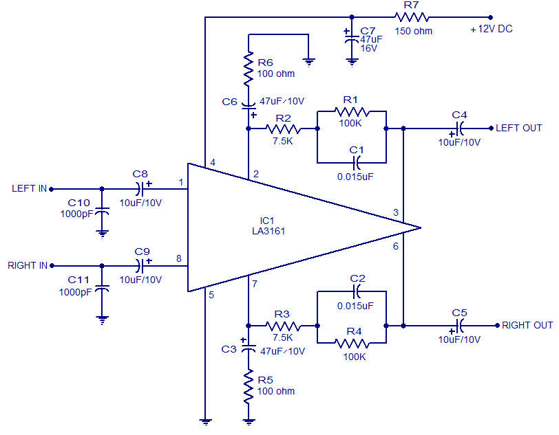
The LA3161 is an integrated two-channel preamplifier designed for car stereo applications. It operates on a 12V DC power supply. The LA3161 preamplifier is specifically engineered to enhance audio signals in automotive environments, ensuring optimal sound quality for car stereo...
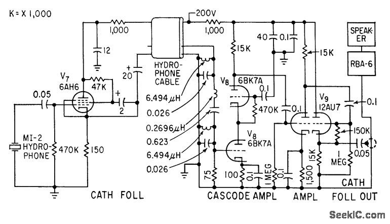
A cathode-follower hydrophone isolation amplifier and high-gain preamplifier are used to feed the Navy RBA-6 low-frequency radio receiver on a trawler. This setup is designed to receive a modulated 21-kc beam that transmits data regarding trawl net depth. The...

Proper grounding is essential for eliminating hum and ground loops. The ground connections for J1, P1, C2, C3, and C4 should all be connected to the same point. Additionally, connect C9 to the output ground. In electronic circuits, grounding serves...
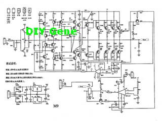
The following circuit illustrates a complete solid-state M-9 power amplifier circuit diagram. Features include a DC servo that acts as a loudspeaker protection circuit. The solid-state M-9 power amplifier circuit is designed to deliver high-quality audio amplification while ensuring the...
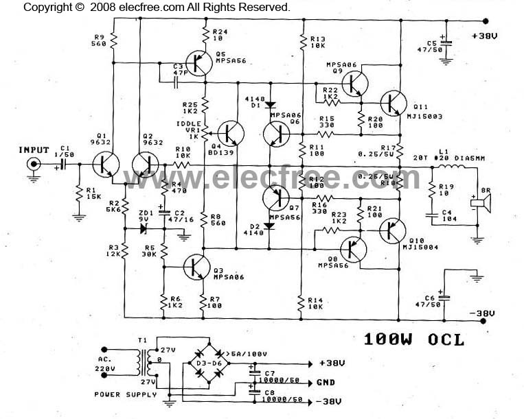
This OCL 100W power amplifier offers excellent sound quality. The circuit features direct coupling throughout to minimize low-frequency cut-off issues, enhancing super bass performance. The input signal for the tone controls enters via capacitor C1 to the base pin...