
color sensor circuit diagram
The color sensor circuit operates on the principle of light absorption and reflection. The three LDRs are sensitive to different wavelengths of light corresponding to the primary colors of red, green, and blue (RGB). Each LDR is paired with a specific colored filter that allows only its corresponding wavelength to pass through while blocking others. This selective filtering enables the circuit to determine the color of the object based on which LDRs are activated.
The output from the LDRs is fed into a logic circuit that interprets the signals. For instance, if only LDR1 (red) is activated, the output will indicate the presence of red. If both LDR1 and LDR2 (red and green) are activated, the output will indicate yellow, showcasing the circuit's ability to detect secondary colors. The logic circuit can be implemented using simple transistor-based gates or more complex microcontroller-based systems, depending on the project's requirements and complexity.
To ensure optimal performance, careful consideration must be given to the placement of the LDRs and lenses. The lenses should be aligned precisely to focus the incoming light onto the LDRs effectively. Additionally, the ambient light conditions should be controlled to prevent interference with the readings, as external light sources can affect the accuracy of color detection.
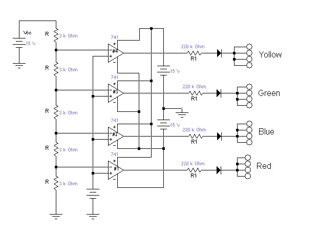
In summary, this color sensor circuit is a versatile tool for robotics and automation applications, allowing for precise color detection through a well-designed optical and electronic system. Proper assembly, calibration, and environmental control are essential for achieving reliable and accurate results in color sensing tasks.This is a color sensor Circuit Diagram. This circuit will sense 8 colors that are:, green, red and blue ; magenta, cyan and yellow ; and black and white. It`s will be very useful for robotics project. The object whose colour is required to be detected should be placed in front of the system. The light rays reflected from the object will fall on t he three convex lenses which are fixed in front of the three LDRs. The convex lenses are used to converge light rays. This helps to increase the sensitivity of LDRs. Blue, green and red glass plates (filters) are fixed in front of LDR1, LDR2 and LDR3 respectively. When reflected light rays from the object fall on the gadget, the coloured filter glass plates determine which of the LDRs would get triggered. When a primary coloured light ray falls on the system, the glass plate corresponding to that primary colour will allow that specific light to pass through.
But the other two glass plates will not allow any light to pass through. Thus only one LDR will get triggered and the gate output corresponding to that LDR will become logic 1 to indicate which colour it is. Similarly, when a secondary coloured light ray falls on the system, the two primary glass plates corres- ponding to the mixed color will allow that light to pass through while the remaining one will not allow any light ray to pass through it.
As a result two of the LDRs get triggered and the gate output corresponding to these will become logic 1 and indicate which color it is. When all the LDRs get triggered or remain untriggered, you will observe white and black light indications respectively.
Following points may be carefully noted : The LDR is mounded in a tube, behind a lens, and aimed at the object. The coloured glass filter should be fixed in front of the LDR as shown in the figure. Make three of that kind and fix them in a suitable case. Adjustments are critical and the gadget performance would depend upon its proper fabrication and use of correct filters as well as light conditions
🔗 External reference
Related Circuits
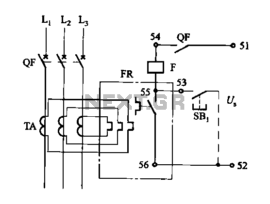
The DK-5A, 5D, and SDb control boxes are equipped with a thermal electromagnetic overcurrent release, as depicted in Figure 6-80. The trip mechanism provides both overload and instantaneous short circuit protection with a long delay feature. In the figure,...
For proper operation, the circuit ground must be connected through a small-value, high-voltage-rated capacitor to one side of the mains supply socket. The "Live" side is the right one. This circuit is designed to animate shop windows using a...
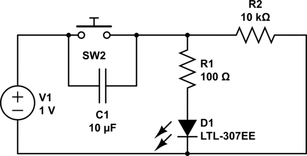
Understand why the LED does not light up, as the capacitor appears to be bypassing the switch. When the capacitor is fully charged, it does not conduct electricity. Although the individual is a beginner, after 20 hours of studying...
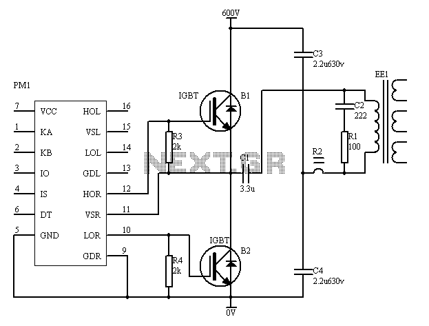
The PM4040F is utilized in switching power supply applications for medium power ranges. It is designed to drive power supplies between 200W and 800W, as illustrated in the accompanying bridge circuit. For power applications below 1000W, an alternative circuit...
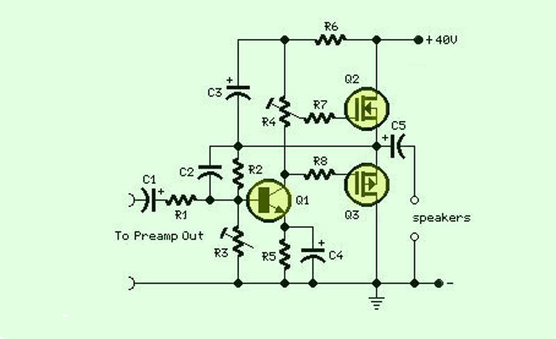
The function of this circuit is an audio amplifier capable of delivering a decent output power with a minimal number of components, with considerable efficiency. This audio amplifier circuit is designed to enhance audio signals, providing sufficient output power while...
The integrated circuit LM386 is a low-power audio frequency amplifier that requires a low-level power supply, typically batteries. It is available in an 8-pin mini-DIP package. The IC is designed to provide a voltage amplification of 20 without the...
Warning: include(partials/cookie-banner.php): Failed to open stream: Permission denied in /var/www/html/nextgr/view-circuit.php on line 713
Warning: include(): Failed opening 'partials/cookie-banner.php' for inclusion (include_path='.:/usr/share/php') in /var/www/html/nextgr/view-circuit.php on line 713