
18 W MOSFET Amplifier Circuit With BC550C Transistor
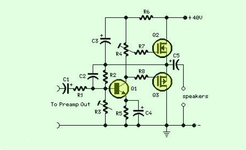
This audio amplifier circuit is designed to enhance audio signals, providing sufficient output power while maintaining a simple and efficient design. The circuit typically consists of a few essential components, including transistors, resistors, capacitors, and a power supply, which work together to amplify the input audio signal.
The core of the amplifier is usually a class AB transistor configuration, which combines the advantages of both class A and class B amplifiers. This configuration allows the circuit to produce high-quality audio output with reduced distortion levels. The transistors are responsible for increasing the input signal's amplitude, while the accompanying resistors and capacitors help to stabilize the circuit and filter out unwanted noise.
The power supply for the amplifier is critical, as it must provide adequate voltage and current to ensure optimal performance. Typically, a dual power supply is employed, allowing the amplifier to function effectively in both positive and negative voltage swings, which is essential for audio signals.
In addition to the basic amplification function, various feedback mechanisms may be incorporated into the circuit to improve linearity and reduce distortion further. This feedback can be achieved through the use of additional resistors and capacitors strategically placed in the circuit design.
Overall, this audio amplifier circuit is an efficient and straightforward solution for amplifying audio signals, making it suitable for various applications, including personal audio systems, small public address systems, and other audio-related projects.The function for this circuit is an audio amplifier capable of delivering a decent output power with a minimum no: of parts , with considerable .. 🔗 External reference
Related Circuits
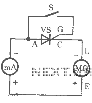
The table illustrates the capability to trigger the thyristor circuit diagram. The thyristor circuit diagram serves as a fundamental component in various electronic applications, particularly in power control and switching. A thyristor is a four-layer semiconductor device that functions as...
Pure Class-A triode OTL design and only one tube for amplification. The plate voltages should be low. The output impedance should be as low as possible and the maximum output current should be as high as possible. This amplifier...
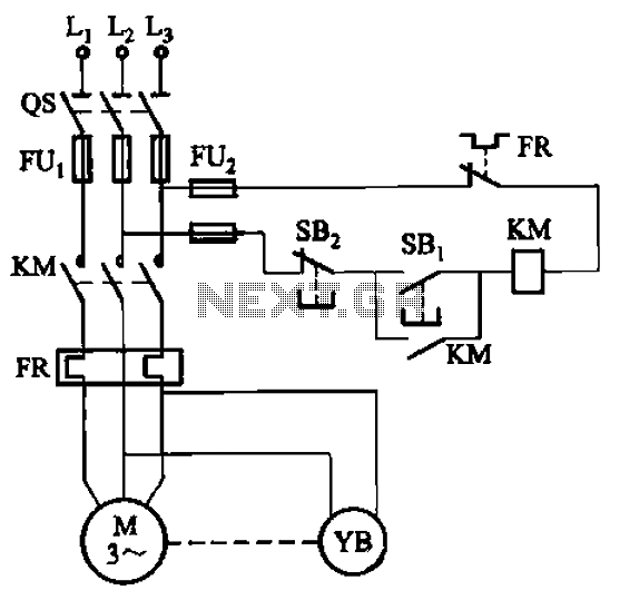
The circuit depicted in Figure 3-121 illustrates the key component of an electromagnetic holding brake, which consists of an electromagnetic brake solenoid primarily made up of two parts: the iron core and the shoe brake components. When power is...
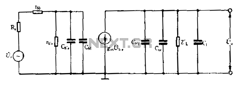
Common emitter amplifier circuit with resistance and capacitance coupling. The common emitter amplifier circuit is a fundamental configuration in analog electronics, widely utilized for its ability to amplify voltage signals. This circuit employs a bipolar junction transistor (BJT) as the...
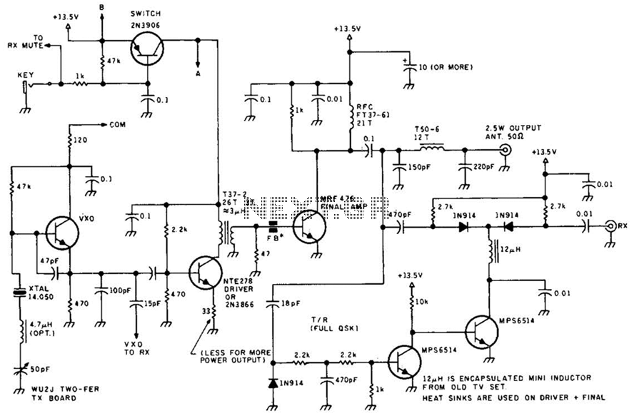
An FM radio generates an interference signal that can be detected on another FM radio tuned 10.7 MHz higher than the original. A 50 kΩ potentiometer is used to adjust the modulation level to its maximum without introducing distortion....
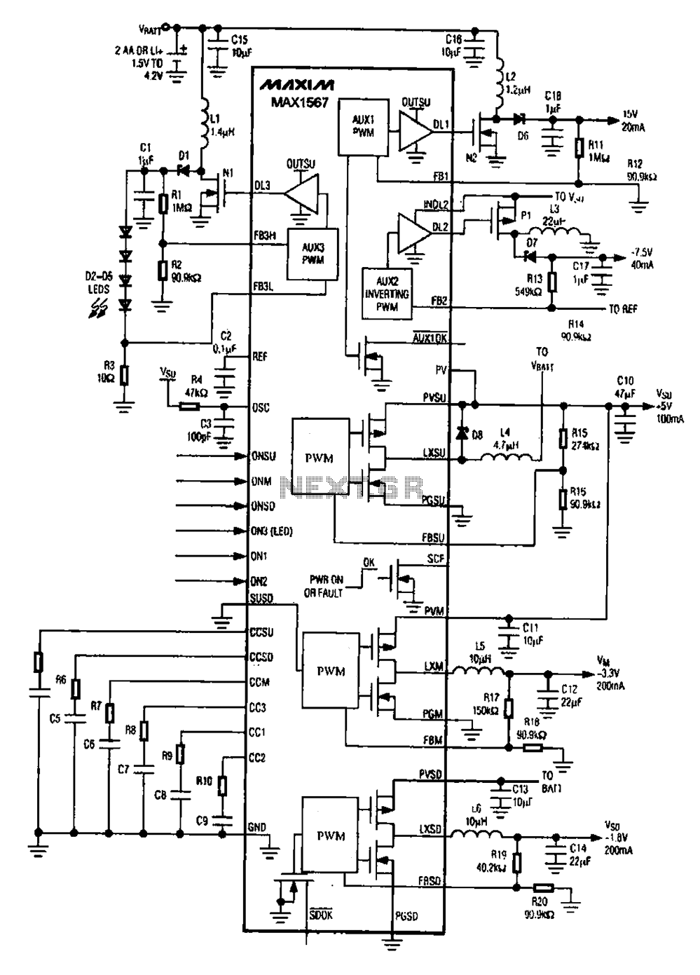
A brush 6-channel camera power supply circuit utilizing the MAX1566/1567. This circuit features a PWM generation system that is divided into six groups, with each group managing a separate channel. The circuit converts the DC voltage from the battery...
Warning: include(partials/cookie-banner.php): Failed to open stream: Permission denied in /var/www/html/nextgr/view-circuit.php on line 713
Warning: include(): Failed opening 'partials/cookie-banner.php' for inclusion (include_path='.:/usr/share/php') in /var/www/html/nextgr/view-circuit.php on line 713