
Combinational Logic Circuits using Logic Gates
Combinational logic circuits are fundamental components in digital electronics, characterized by their ability to produce outputs based solely on the current inputs, without any memory of past inputs. These circuits employ various logic gates, such as AND, OR, NOT, NAND, NOR, XOR, and XNOR, to perform logical operations and implement complex functions.
Multiplexers, also known as data selectors, are devices that take multiple input signals and select one of them to be sent to the output based on the values of select lines. A typical multiplexer is designed with a specific number of inputs and outputs, along with control lines. For example, a 2-to-1 multiplexer has two input lines, one output line, and one control line. The output reflects the value of the selected input, depending on the state of the control line.
Encoders are another type of combinational logic circuit that converts input signals into coded output signals. For instance, a binary encoder takes multiple input lines and produces a binary representation of the active input. A common example is the 4-to-2 encoder, which has four input lines and produces a two-bit binary output corresponding to the active input line.
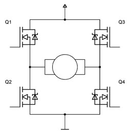
Solid-state switches utilize similar principles as traditional mechanical switches but are based on semiconductor devices. These switches can control the flow of current in a circuit with high reliability and speed, making them ideal for applications in automation and control systems. Solid-state switches can be implemented using transistors or other semiconductor devices, providing advantages such as reduced wear and tear compared to mechanical switches.
Overall, the study of combinational logic circuits and their applications in multiplexers, encoders, and solid-state switches is crucial for designing efficient digital systems and contributes significantly to advancements in electronics and computing technology.Electronics Tutorial about Combinational Logic Circuits that use Logic Gates to make Multiplexers, Encoders and Solid State Switches.. 🔗 External reference
Related Circuits
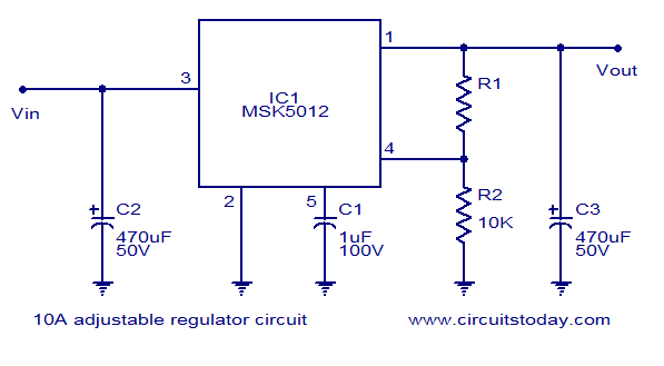
A reliable 10A adjustable voltage regulator based on the MSK5012, featuring an output voltage range of 1.3 to 30V. It is characterized by low ripple and high efficiency. The MSK5012 adjustable voltage regulator is designed for applications requiring a stable...
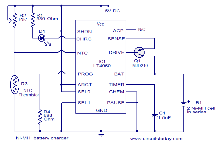
This circuit diagram represents a highly efficient Ni-MH battery charger utilizing the LT4060 integrated circuit from Linear Technologies. The circuit can also accommodate Ni-Cd batteries with minor modifications. To charge Ni-Cd batteries, the CHEM pin (pin 12) of the...
This amp delivers a lot of power and uses 1 IC and two power transistors. The circuit consists of an amplifier IC (a TDA 2030A) and a power stage consists of two transistors. The amplifier can be powered with...

Another application of the frequency-to-voltage converter (FVC) is the tone/frequency decoder. This circuit is designed to identify the frequency band of an oscillating signal. It is utilized in various applications, such as determining the frequency band in signals and...
This circuit detects the dial tone from a telephone line and decodes the keypad pressed on the remote telephone. The dial tone heard when picking up the phone is known as Dual Tone Multi-Frequency (DTMF). The term is derived...
The project involves a DC geared motor intended for use in a suitcase carrier. Two motors were purchased from Pololu at a cost of approximately $100. The selection process included discussions among team members, followed by consultation with Dr....