
40W audio amplifier using TDA2030
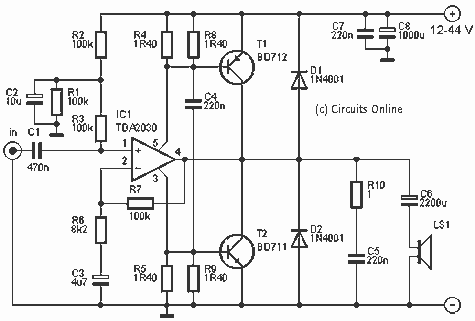
The described audio amplifier circuit utilizes a TDA2030A integrated circuit as its core amplification component. This IC is known for its ability to deliver substantial output power while maintaining low distortion, making it suitable for various audio applications. The circuit is designed to operate with an asymmetric power supply voltage ranging from 12V to 44V, allowing flexibility in power source selection.
The power stage of the amplifier incorporates two pairs of transistors, specifically the BD712 and BD912 for one half of the output stage, and BD711 and BD911 for the complementary side. These transistors are configured to enhance the output current capability of the amplifier, enabling it to drive speakers with impedances of 4 to 8 ohms effectively.
The components listed in the parts list play critical roles in the circuit's operation. Resistors R1, R2, R3, and R7, all rated at 100 kOhm, are likely utilized for biasing and feedback purposes. R6, with a resistance of 8.2 kOhm, may be part of a feedback loop or used for input impedance matching. The resistors R4, R5, R8, and R9, each rated at 1.40 ohms with a tolerance of 1%, are likely used in the output stage to limit current and protect the transistors from excessive load.
Capacitors C1 through C8 serve various functions including coupling, decoupling, and filtering. C1, a 470 nF capacitor, is likely used for signal coupling, while C2 (10 µF/63V) and C3 (4.7 µF/63V) may be used for power supply decoupling, ensuring stable operation by filtering out high-frequency noise. Capacitors C4, C5, and C7 (220 nF) are typically used for bypassing or coupling, while C6 (2200 µF/50V) and C8 (1000 µF/50V) provide bulk capacitance to stabilize the power supply rail.
Diodes D1 and D2 (1N4001) are used for protection, likely to prevent back EMF from damaging the transistors. The cooling requirements of the circuit are addressed by a Fisher SK08/75 heatsink, which is essential for dissipating heat generated by the power transistors during operation, ensuring reliability and longevity of the amplifier.
Overall, this circuit design demonstrates a well-thought-out approach to audio amplification, combining a robust integrated circuit with complementary transistors to achieve a powerful and efficient audio output.This amp delivers a lot of power and uses 1 IC and two power transistors. The circuit consists of an amplifier IC (a TDA 2030A) and a power stage consists of two transistors. The amplifier can be powered with an asymmetric voltage of 12-44 V. Parts List R1-R3, R7 = 100 kOhm R6 = 8.2 kOhm R4, R5, R8, R9 = 1.40 ? 1% R10 = 1 ? C1 = 470 nF C2 = 10 V ?F/63 C3 = 4.7 V ?F/63 C4, C5, C7 = 220 nF C6 = 2200 V ?F/50 C8 = 1000 V ?F/50 D1, D2 = 1N4001 T1 = BD712 and BD912 T2 = BD711 and BD911 IC1 = TDA2030A LS = speaker - 4 / 8 ? cooling = Fisher SK08/75 🔗 External reference
Related Circuits
An embedded system designed for tracking and positioning vehicles utilizes the Global Positioning System (GPS) and the Global System for Mobile Communication (GSM). This project employs the AT89S52 microcontroller to interface with various hardware peripherals. The system continuously monitors...
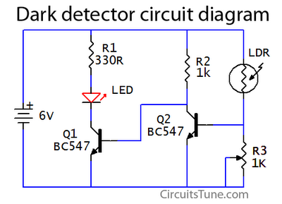
This is a basic dark detector or sensor circuit diagram based on a photoresistor (LDR) and a few components. The dark detector circuit utilizes a photoresistor (LDR) as the primary sensing element. The LDR is a light-dependent resistor that changes...
The gain of the low-cost integrated circuit (IC) is internally fixed at no less than 34 dB (50 times). A unique input stage allows input signals to be referenced to ground. The output is automatically self-centering to one-half the...
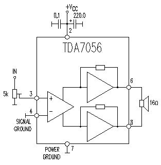
This TDA7056 power audio amplifier circuit diagram project is designed to deliver a maximum output power of 1 watt into an 8-ohm load when powered by a 6-volt supply, or a maximum output power of 3 watts into a...
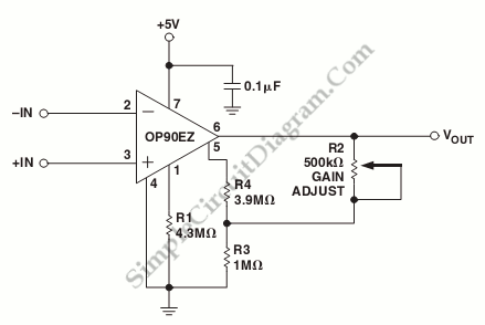
A schematic diagram of a micropower single-supply instrumentation amplifier circuit is presented. This circuit requires only 15µA of current and can provide over... The micropower single-supply instrumentation amplifier circuit is designed for applications where low power consumption is critical. The amplifier...
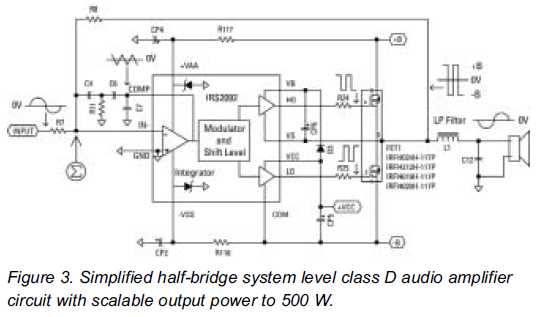
Class D audio amplifiers are now prepared to replace Class AB amplifiers. An integrated high-voltage audio driver simplifies the design and construction of high-power audio systems. Class D audio amplifiers, also known as switching amplifiers, utilize pulse-width modulation (PWM) to...
Warning: include(partials/cookie-banner.php): Failed to open stream: Permission denied in /var/www/html/nextgr/view-circuit.php on line 713
Warning: include(): Failed opening 'partials/cookie-banner.php' for inclusion (include_path='.:/usr/share/php') in /var/www/html/nextgr/view-circuit.php on line 713