
Comes with rechargeable lead-acid battery LED emergency light circuit diagram
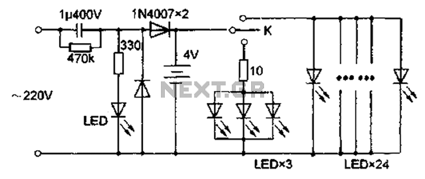
The circuit operates by converting 220V AC into a usable DC voltage suitable for charging a lead-acid battery. The capacitor serves to smooth out the rectified voltage, while the buck converter efficiently reduces the voltage to the appropriate level for charging. The diode rectifier ensures that the current flows in the correct direction, preventing damage to the battery. The inclusion of a red LED serves as a visual indicator of the charging process, providing users with immediate feedback on the operational status.
The design incorporates a button switch (K) that activates the charging circuit. Once engaged, the circuit initiates a sequence where a three-color flashing LED becomes operational, creating an attractive light display. This feature not only serves as an aesthetic enhancement but also increases visibility in low-light conditions. Following this, a series of 24 bright LEDs are illuminated in parallel, significantly boosting the overall brightness.
The initial design allowed for a high current draw of 600mA for the bright LEDs, which, while providing intense illumination, posed a risk to the longevity of the lead-acid battery. To address this, a current limiting resistor was added to the LED circuit. This adjustment effectively reduced the operating current to 320mA without a noticeable decrease in brightness, thereby balancing performance with battery health.
The analysis of existing LED lamp circuits reveals a trend toward overly simplistic designs that may compromise energy efficiency. By implementing thoughtful modifications, this circuit retains its cost-effectiveness and portability while improving safety and reliability. The enhancements ensure that the circuit not only meets user needs for illumination but also aligns with best practices in energy consumption and battery maintenance.According to kind of draw the circuit diagram shown in Figure 5, 220V AC power after the capacitor buck diode rectifier to lead-acid battery charging, the red LED for charging instructions. Close button switch K charged after use, first turn on three color flashing LED, issued fantastic vagaries of colorful light at night added some of the pleasures of life, and click the switch K is closed color flashing LED, then then only turned 24 in parallel with bright LED, due to the relatively large number of very good lighting effects. When the lead-acid battery voltage of 4V, lantern measured operating current of about 60mA, bright LED currents as high as 600 mA.
Such a large current lighting not only makes each time not too long when fully charged, and the internal structure of the battery will damage and shorten life, it is necessary to highlight the LED string into a small value current limiting resistor, after repeated selected test circuit diagram omitted 1.2 eventually reduced operating current 320mA, and the brightness change is not obvious, because the modifications are minor lights which, after the transformation. Through the above analysis found that the market for sale a variety of LED lamp circuit mostly too simple, although the price is very cheap, but the objective will result in waste of energy, and only after some reasonable improvements to retain the advantages of both its economic and portable, and effectively improve the safety and reliability.
Related Circuits
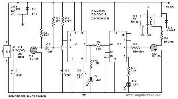
The circuit diagram of a remote-controlled appliance switch circuit includes two main components: IC1 (NE 555) and IC2 (CD 4017). The remote-controlled appliance switch circuit is designed to allow users to control electrical appliances wirelessly. The heart of this circuit...
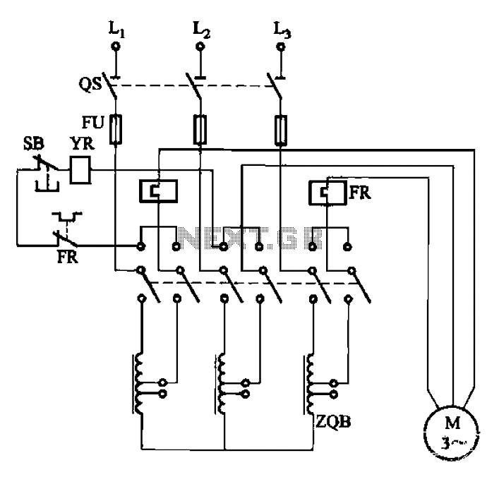
The circuit illustrated in Figure 3-47 involves a three-phase AC motor that is initially connected through a step-down autotransformer. To initiate operation, the power switch is closed, and the operating handle is pushed to the start position. Once the...
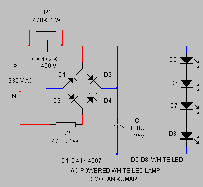
The circuit provides sufficient illumination suitable for reading purposes. Capacitor CX, in conjunction with diodes D1 through D4, constitutes the AC step-down circuit. CX lowers the high voltage AC from the mains to a low voltage AC, which is...

Build a personal data logger for recording analog signals. The MiniLOGGER provides 8-channel analog input (-99mV to +999mV), 1-channel pulse input, battery backup with 256kB SRAM, a Real-time Clock, and RS232C communication. Recording can be initiated or stopped using...

Most PN-junction diodes can be utilized as photodiodes. Although they are not specifically optimized for this purpose, they are functional. When reverse biased, a diode generates a small photovoltaic output that increases with light intensity. Light Emitting Diodes (LEDs)...

This circuit generates a siren sound when switch S1 is pressed. The sound frequency increases as capacitor C1 charges, and when switch S1 is released, the frequency decreases as capacitor C1 discharges. The circuit operates on a simple principle of...