
Remote Controlled Appliance Switch Circuit

The remote-controlled appliance switch circuit is designed to allow users to control electrical appliances wirelessly. The heart of this circuit is the NE 555 timer (IC1), which is configured in a monostable mode. This configuration enables the circuit to produce a single output pulse in response to a trigger signal. The output from the NE 555 timer can be used to activate other components in the circuit.
The CD 4017 (IC2) is a decade counter that serves as a secondary component in this circuit. It counts the pulses from the NE 555 timer and can control multiple outputs. This allows for the switching of various appliances based on the number of pulses received. The outputs of the CD 4017 can be connected to relay modules, which in turn control the power to the appliances.
The circuit typically includes additional components such as resistors, capacitors, and diodes to ensure proper functioning and to protect against voltage spikes. The NE 555 timer requires a stable power supply, and decoupling capacitors may be added to filter any noise on the power lines.
The remote control aspect of the circuit can be achieved through the use of an infrared (IR) transmitter and receiver, which can send the trigger signal to the NE 555 timer. The user can activate the appliance by pressing buttons on the remote control, which sends a command to the circuit, causing the NE 555 to generate a pulse and trigger the CD 4017.
This design allows for flexibility in controlling various appliances from a distance, making it suitable for home automation applications. The circuit can be expanded by adding more output devices or integrating it with other control systems, further enhancing its functionality in a smart home environment.Here is the circuit diagram of remote controlled appliance switch circuit. The main parts of this circuit are IC1 (NE 555), IC2 (CD 4017). 🔗 External reference
Related Circuits

This design outlines a simple wideband output amplifier suitable for use as a 50-ohm transmission line driver. The circuit is constructed using the CA3140 operational amplifier. When utilized alongside the function generator and sine wave shaper circuits, it delivers...
A typical circuit for welding equipment is illustrated in the following circuit diagram. The turn-on delay can be accurately controlled with Potentiometer P2, allowing for effective discharge management. The welding equipment circuit typically incorporates several key components to ensure proper...
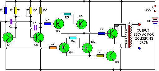
This is a simple and cost-effective inverter designed for small soldering irons (25W, 35W, etc.) to be used in the absence of mains supply. The circuit employs eight transistors along with a few resistors and capacitors. Transistors Q1 and...
The objective of this project was to design a small portable mixer powered by a 9V PP3 battery while maintaining performance quality. The mixer consists of three main modules that can be varied in number and can be adapted...
The telephone repeater is a circuit designed to amplify the call signal, making it louder than the original. This circuit has been developed in response to specific requests. The telephone repeater circuit functions by receiving the incoming audio signal from...
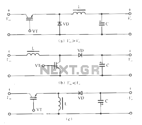
The circuit operates without isolation for both input and output voltage, utilizing a working switch along with an inductor (L), diode (D), and capacitor (C) to form a basic inverter circuit. There are three types of converters: the step-down...