
Commercial Stand-Light
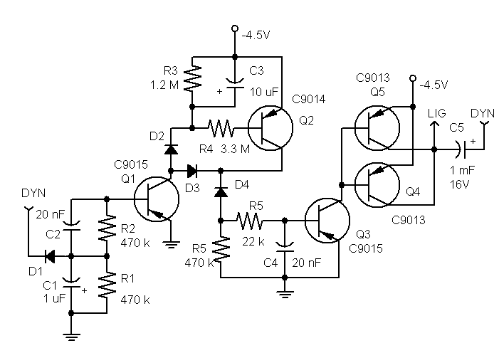
The circuit design incorporates a 1000 µF capacitor (C5) which plays a crucial role in managing power delivery to the lighting system. The capacitor acts as a buffer, allowing the lights to remain illuminated during brief interruptions in dynamo operation, particularly at low speeds. The choice of a larger capacitance value helps to smooth out fluctuations in voltage, particularly important for hub dynamos that may experience more significant drops in output at lower rotational speeds.
The charging sequence begins with the dynamo producing voltage, which is directed through diode D1 to charge capacitor C1. When C1 reaches a sufficient voltage, it activates transistor Q1. The activation of Q1 is pivotal as it initiates the charging of capacitor C3. The charging of C3 subsequently activates transistor Q2, which allows current to flow through the circuit, thereby powering the lights via the path that includes D3 and Q1.
In the event that the dynamo stops producing power, the rapid discharge of capacitor C1 results in the deactivation of Q1. However, the charge retained in C3 keeps Q2 active for a brief period. The current now redirects through resistor R5, allowing transistor Q3 to turn on. This action triggers transistors Q4 and Q5, which are configured in parallel to handle the load without risking damage to individual components. This parallel configuration is essential, as it distributes the current load, ensuring that neither transistor exceeds its rated maximum current of 0.5 A.
As capacitor C3 discharges, it eventually reaches a point where Q2 turns off, leading to the sequential deactivation of Q3, Q4, and Q5, effectively cutting power to the lights. This design ensures a reliable light source while maintaining the integrity and safety of the circuit components, making it suitable for various applications where dynamo-powered lighting is required.An interesting feature in this stand-light is the use of the 1000 uF capacitor C5 connecting the dynamo to the lights. The capacitor will be cutting off the power to the lights at low speeds. For a bottle dynamo, these would be such low speeds that the effect should be irrelevant. However, the effect may become unacceptable for a hub dynamo that operates at lower frequencies than bottle. Anyway, the circuit operates as follows. An operating dynamo charges the capacitor C1 through D1. This turns Q1 on. When Q1 is on, it charges the capacitor C3 which puts Q2 on. As long as Q1 is on, the current through Q2 flows through D3 and Q1. When the dynamo stops, C1 quickly discharges putting Q1 off. With C3 remaining charged, Q2 continues to be on, but now the current flows no more through Q1 that is off, but through R5. This puts Q3 on, which switches on Q4 and Q5 that connect the battery to the lights. After C3 discharges, Q2 goes off and so do Q3-Q5. Q4 and Q5 are connected in parallel because the use of one such transitor, with a max current ICE of 0.
5 A, would put that transistor too close to the boundary of its safe operation. 🔗 External reference
Related Circuits
A voltage-controlled oscillator (VCO) is an electronic signal generator that produces a signal with a variable frequency, which is dependent on an input voltage level. A voltage-controlled oscillator is a fundamental component in various electronic applications, including phase-locked loops (PLLs),...
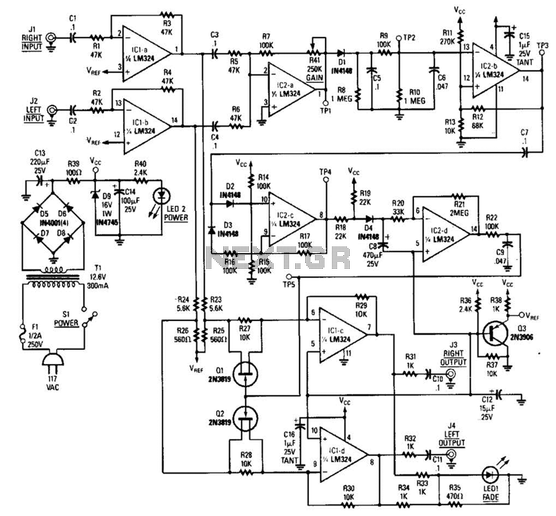
The LR inputs are summed, processed, and then drive a comparator. This comparator detects levels and generates transitions when audio inputs exceed or fall below predetermined thresholds. The frequency of these transitions, which correspond to rapid volume changes, is...
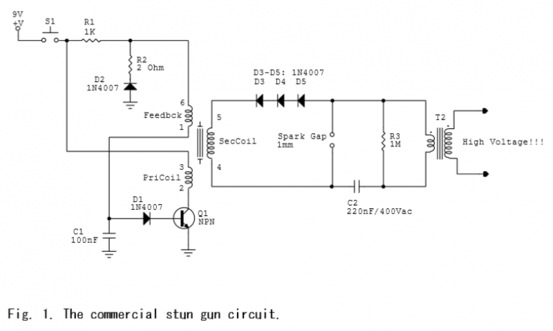
A commercial stun gun circuit that generates approximately 100 kV pulses from a 9V battery is illustrated in Figures 1-2. The core of the circuit is a power oscillator centered around transistor Q1. When switch S1 is activated, capacitor...