
Radio Commercial Zapper Circuit
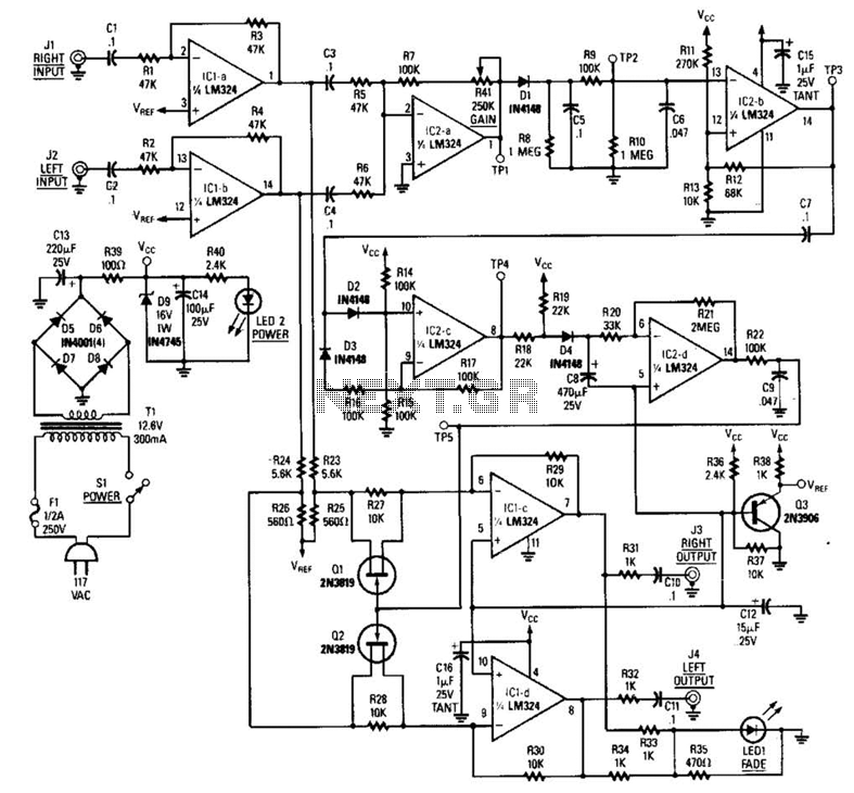
The circuit described implements a dynamic range sensing mechanism that operates by summing left (L) and right (R) audio inputs. The summed signal is then fed into a comparator, which continuously monitors the amplitude of the audio signal against set threshold levels. When the audio signal exceeds these thresholds, the comparator generates a transition signal, indicating a significant change in audio level.
The transition signals produced by the comparator are indicative of rapid fluctuations in audio volume. These transitions are then integrated to create a smooth control signal that reflects the average level of the audio dynamics over time. This integrated signal is crucial as it serves to modulate the gain of two voltage-controlled amplifiers (VCAs), allowing for dynamic adjustment in amplification based on the audio signal's envelope.
The envelope detection is a key feature of this circuit, as it ensures that the control signal derived from the audio input accurately represents the variations in signal amplitude. The pulse rate generated from the integrated signal at IC2-C is directly related to the audio envelope, allowing for precise control over the VCA gain settings. This method enables the circuit to adaptively respond to changes in audio levels, enhancing the overall dynamic range management of the audio system.
In summary, this circuit effectively combines summation, level detection, transition generation, integration, and gain control to create a responsive audio processing system that can dynamically adjust to varying audio levels, ensuring optimal performance and sound quality. The LR inputs are summed, dated and drive a comparator. The comparator senses level and generates a transition when audio inputs go above or below preset thresholds. The number of these transitions (corresponding to rapid volume changes) are integrated and feed voltage controlled amplifiers.
This device actually senses dynamic range. BLOCK DIAGRAM OF THE COMMERCIAL KILLER: The envelope of the signal is used to vary the pulse rate from IC2-C. The pulses are integrated; the resulting signal controls the gains of a pair of VCA`s. 🔗 External reference
Related Circuits
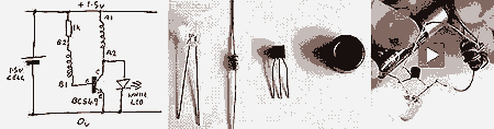
This circuit can be utilized in various devices to extract residual energy from seemingly depleted batteries. It is possible to connect multiple dead batteries in order to maximize energy extraction. This circuit design, often referred to as a Joule Thief,...
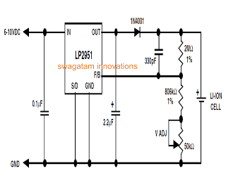
Unlike lead-acid batteries, one advantage of lithium-ion (Li-Ion) batteries is that they can be charged at a 1C rate initially. This means the charging current can be as high as the rated ampere-hour (AH) capacity of the battery at...
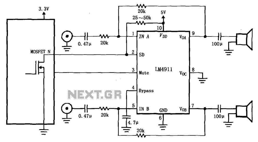
The circuit for the LM4911 demonstrates different power conduction times. It utilizes a controller, specifically the MOSFET LM4911 shutdown control (SD) terminal, to regulate the on-time of the amplifier. The LM4911 is a power amplifier designed for audio applications, providing...
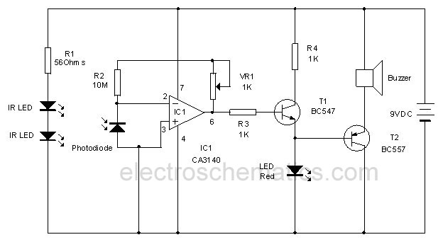
This circuit utilizes invisible infrared light to detect the movement of individuals through a doorway. A brief beep will be emitted when the infrared beam is interrupted. The infrared movement detection circuit employs an infrared LED and a photodiode or...
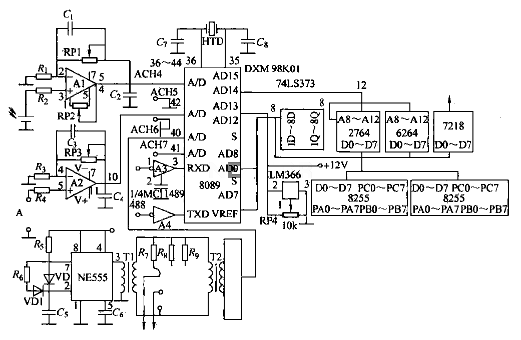
Direct measurement circuit for soil content, assessing various parameters such as moisture, salinity, nitrogen, and pH to enhance soil quality for diverse agricultural crops. This electronic measuring circuit facilitates rapid and accurate testing of soil conditions and informs fertilization...
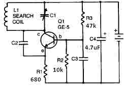
This metal detector circuit requires a power supply of 9 volts (DC) or a 9-volt battery. The circuit includes a variable capacitor C1 valued at 365 pF, a 100 pF silver mica capacitor C2, a 0.05 µF disc capacitor...
Warning: include(partials/cookie-banner.php): Failed to open stream: Permission denied in /var/www/html/nextgr/view-circuit.php on line 713
Warning: include(): Failed opening 'partials/cookie-banner.php' for inclusion (include_path='.:/usr/share/php') in /var/www/html/nextgr/view-circuit.php on line 713