
Common collector amplifier via a DC and AC
The common collector amplifier, also known as an emitter follower, is characterized by its ability to provide high input impedance and low output impedance. This configuration is particularly useful in applications where signal buffering is required. The DC analysis of the circuit involves determining the quiescent operating point, which is essential for ensuring that the transistor operates within its active region. The biasing network typically consists of resistors that set the base voltage, allowing for proper transistor operation.
In the AC analysis, the coupling capacitors are crucial as they block DC components while allowing AC signals to pass through. This ensures that the amplifier can respond to varying signal levels without affecting the DC bias point. The output signal, taken from the emitter, is a faithful reproduction of the input signal but with a lower voltage level, making it suitable for driving low-impedance loads.
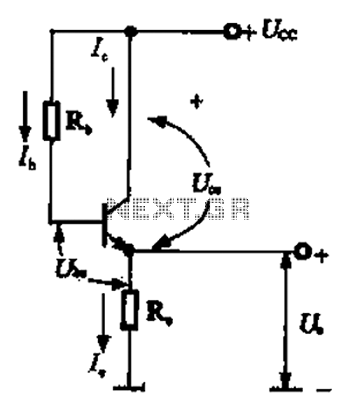
The performance of the common collector amplifier can be further enhanced by considering factors such as temperature stability, frequency response, and power supply variations. Proper selection of components, including the transistor type and biasing resistors, is essential for optimizing the amplifier's characteristics for specific applications. Overall, the common collector amplifier serves as an effective solution for signal amplification and impedance matching in various electronic circuits. Common collector amplifier via a DC and AC (3) common-collector amplifier circuit DC and AC path when common collector amplifier circuit for analysis, can be divided into DC an d AC two paths shown in Figure 1-14. The DC path to provide a DC bias circuit of the circuit from the power transistor, the transistor is in an enlarged state or the off state, it is mainly determined by the bias. This circuit also provides energy for the transistor circuit. AC AC signal path is functioning circuit, a capacitor AC signal can be regarded as a short circuit, the internal resistance of the power supply also depends on the AC signal is short-circuited.
Related Circuits
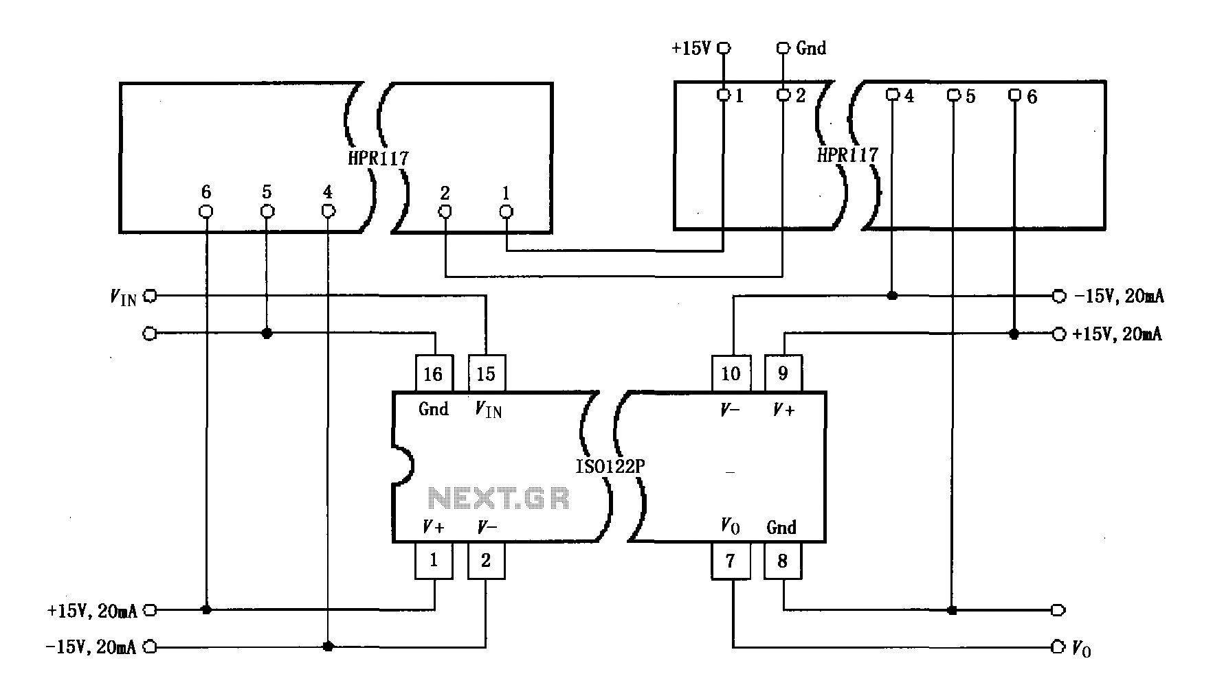
Power isolation is demonstrated for the ISO122P / 124, which features a three-port amplifier. The circuit also utilizes precision analog isolation amplifiers. The ISO122P / 124 isolation amplifier is a cost-effective solution, and the HPR117 DC/DC converter component provides...
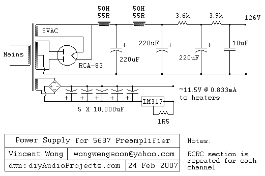
The RCA-83 rectifier utilizes 5VAC for the filament supply. The heaters for the 5687 tubes are powered by a full bridge rectifier consisting of MUR860 diodes, followed by five 10,000µF Elna capacitors. Current regulation is achieved through an LM317...
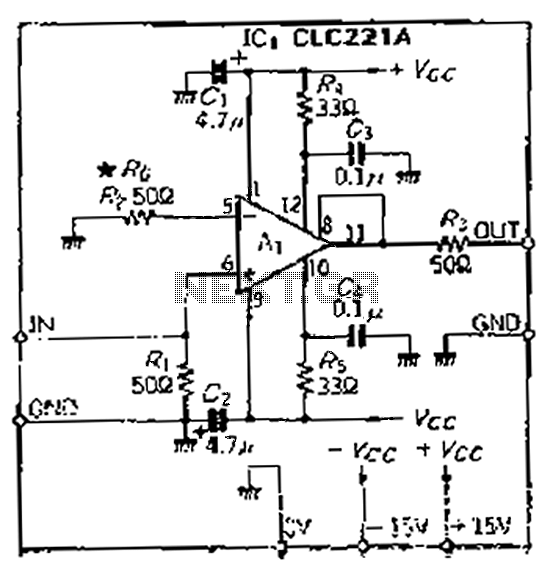
The CLC221A is designed with a traditional operational amplifier (OP) configuration. It is a high-performance current-feedback amplifier capable of operating in both non-inverting and inverting modes. The amplifier features a flat-rate characteristic, which is particularly effective when configured in...
Output-clamp diodes are mandatory because loudspeakers are inductive loads. Output LR isolation is also used because audio amplifiers are usually expected to handle up to 2 mF load capacitance. Large, supply-bypass capacitors located close to the IC are used...
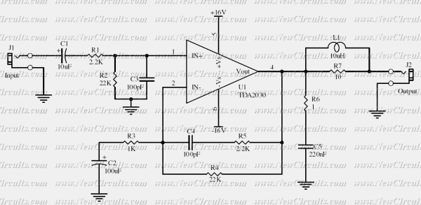
This simple 10 watts audio power amplifier is designed for home-brewed purpose. It is based on an Audio Power Amplifier IC that is called TDA2030. It is a monolithic integrated circuit in Pentawatt package, intended for use as a...
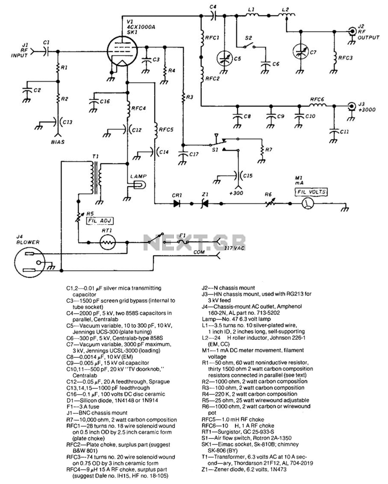
The frequency range of this amplifier is 1.8 to 54 MHz. The required RF drive for full output is approximately 30 W. The grid compartment (Rl, R2, RFC4, RFC5) must be shielded from other circuitry, particularly the output circuitry....
Warning: include(partials/cookie-banner.php): Failed to open stream: Permission denied in /var/www/html/nextgr/view-circuit.php on line 713
Warning: include(): Failed opening 'partials/cookie-banner.php' for inclusion (include_path='.:/usr/share/php') in /var/www/html/nextgr/view-circuit.php on line 713