
Comparison of various circuit diagram VI conversion and a constant current source

The described circuit utilizes multiple load resistors (RL) to achieve various constant current outputs, each configured for specific applications. The floating first RL is typically avoided due to its lack of utility, while the second RL, acting as a virtual ground, is seldom employed in practical scenarios. The third RL, however, is commonly connected to a positive power supply, facilitating more frequent use in applications requiring stable current.
The fourth RL introduces a positive feedback mechanism, which is grounded and preferred for its stability in maintaining constant current outputs. This configuration is particularly advantageous in applications where load variations are expected, as it helps maintain output consistency. The fifth RL builds upon the principles of the fourth, enhancing the circuit's current output capacity, making it suitable for heavier loads. This allows users to directly connect load resistor R2 to RL, often omitting the need for a follower amplifier, thus simplifying the design.
The circuit's ability to maintain constant current is critically dependent on the balance of positive and negative feedback. Any discrepancies in resistance or loss of balance can lead to variations in output current, which can adversely affect performance. In scenarios where the output current does not match the expected values, or where the collector and emitter currents of the transistor do not align, utilizing MOSFETs may provide a more effective solution due to their superior characteristics in managing current flow.
In summary, the circuit's design emphasizes flexibility and reliability in providing constant current outputs across various configurations of load resistors. Its ability to accommodate different loads while maintaining stable performance makes it a valuable asset in electronic applications requiring precise current management. As shown, the circuit can get several constant current output to the load resistor RL. Since the first RL floating, rarely used. The second RL is a virtual ground, do not often use. Although RL third floating, but a termination RL positive power supply terminal, more commonly used. The fourth is a positive feedback balanced, due to the load RL ground and loved by the people. The fifth and fourth on the same principle, but expanded the current output capacity, large multi-use people often take over the load resistor R2 RL, omitted follower amplifier. The fifth is a circuit I would like also to ground load, two are behind the constant current source circuit.
Comparison of several V/I circuit, those who are not just one-way devices like transistors, can achieve constant exchange, after the addition of the transistor can only do a unidirectional DC current. The fourth and fifth are built on the basis of balanced positive and negative feedback, and if the error due to the resistance and loss of balance, will affect the constant current output characteristic, that is, the output current will vary with load.
And several other resistance error affects only the value of the output current, without affecting the output characteristics, if the output current, or collector current and the emitter current of the transistor is not equal too, can be replaced by transistors MOSFET.
Related Circuits
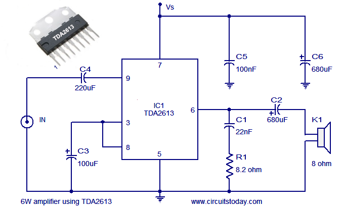
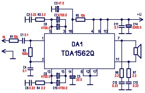
A simple and easy-to-build Hi-Fi audio power amplifier circuit is presented here. This 6-watt Hi-Fi audio amplifier circuit utilizes the TDA2613 integrated circuit (IC). The circuit design employs the TDA2613, which is a high-performance audio amplifier IC known for its efficiency...
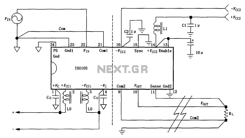
The basic connection circuit for the ISO103 signal and power supply is illustrated. Each power supply terminal must include a bypass filter. If the isolated power supply output current exceeds 15mA, it is advisable to utilize an external filter...
The name of our game, LED Zeppelin, is a play on words. It comes not from the pop group of the same name but from Graf Von Zeppelin, a German who invented the first rigid air ship in 1900....
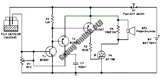
This design features a simple circuit for a tilt sensor alarm that can be constructed using readily available and inexpensive components. The circuit is based entirely on transistor technology. The homemade tilt sensor for this circuit utilizes a standard...
The integrated circuit LM386 is a low-power audio frequency amplifier that requires a low-level power supply, typically batteries. It is available in an 8-pin mini-DIP package. The IC is designed to provide a voltage amplification of 20 without the...
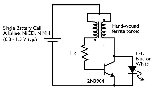
This circuit is commonly referred to as a Joule Thief, and it has been frequently encountered in various electronics videos on YouTube. The Joule Thief is a simple, low-cost circuit designed to extract energy from a single-cell battery, particularly when...