
Audio power amplifier circuit using Hi Fi audio amplifier IC TDA2613
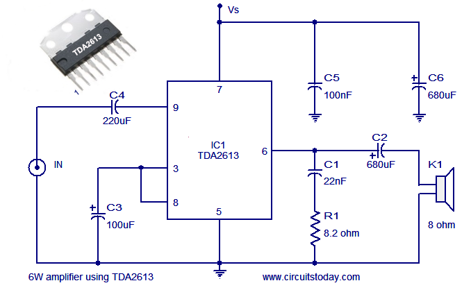
The circuit design employs the TDA2613, which is a high-performance audio amplifier IC known for its efficiency and sound quality. It is capable of delivering up to 6 watts of output power, making it suitable for driving small speakers in various audio applications. The TDA2613 features built-in thermal protection and short-circuit protection, enhancing the reliability of the amplifier.
The basic configuration of the circuit includes the TDA2613 connected to a power supply, typically ranging from 12V to 18V, depending on the desired output power and speaker impedance. Input audio signals are fed into the amplifier through capacitors that block any DC offset, ensuring only the AC audio signal is amplified. The output stage of the amplifier is designed to drive a load, such as an 8-ohm speaker, providing clear and dynamic sound reproduction.
Additional components in the circuit may include resistors for gain adjustment, capacitors for filtering and stability, and a heat sink attached to the TDA2613 to dissipate heat generated during operation. Proper layout and grounding techniques are essential to minimize noise and ensure optimal performance of the amplifier.
This Hi-Fi audio amplifier circuit is ideal for hobbyists and audio enthusiasts looking to build a compact and efficient amplifier for personal audio projects.A simple and easy to build Hi Fi audio power amplifier circuit is shown here. This 6 watt hi Fi audio amplifier circuit uses TDA2613 IC.. 🔗 External reference
Related Circuits
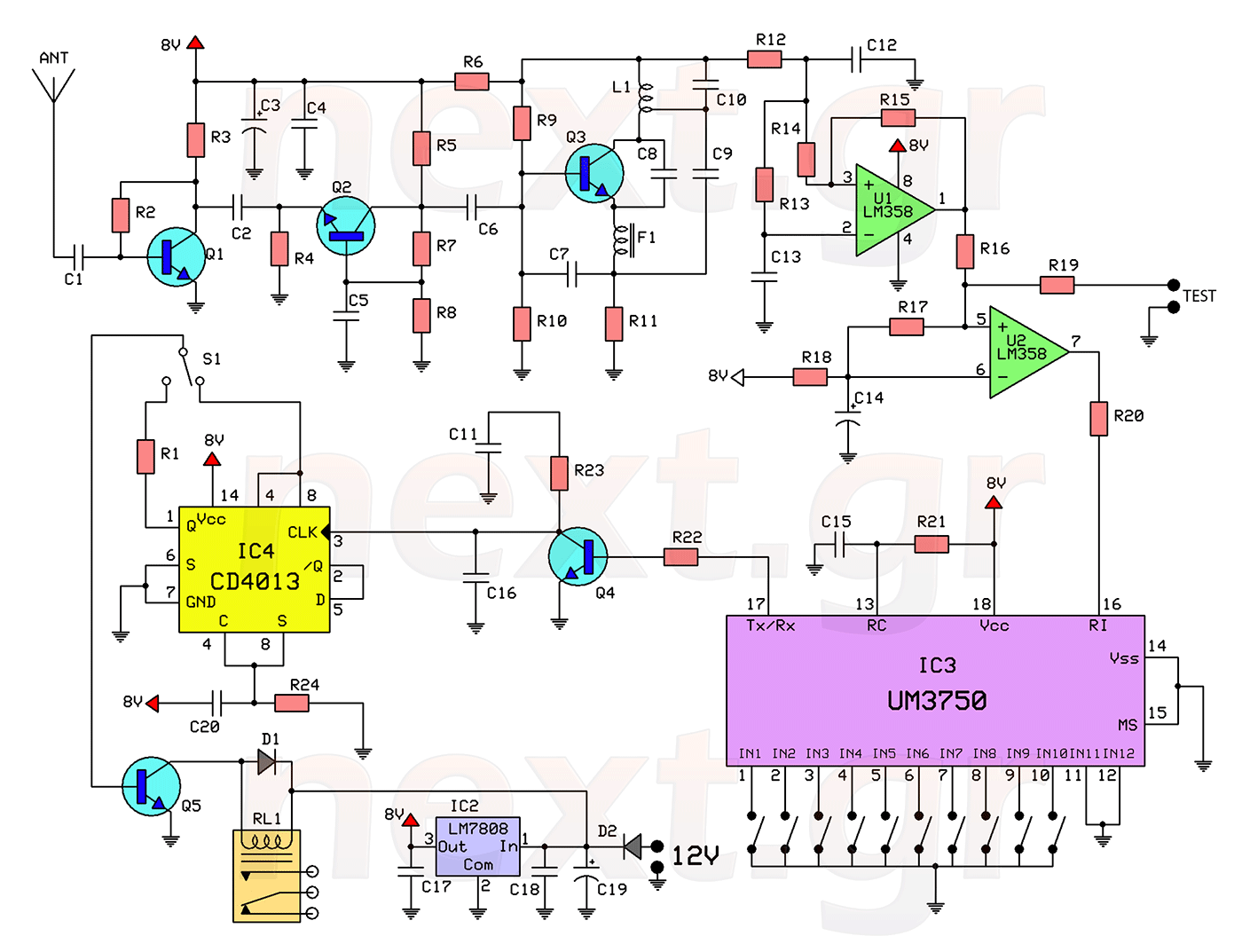
This circuit includes a 2048 radio remote control transmitter and a corresponding wireless receiver that features high reception sensitivity and low power consumption. The combination of these two components provides a highly reliable remote control system, suitable for various...
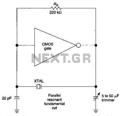
The CMOS amplifier is biased into the linear region by resistor RB. The pi-type crystal network (C1 and C2, and XTAL) provides the 180-degree phase shift at the resonant frequency, which causes the circuit to oscillate. The described circuit utilizes...
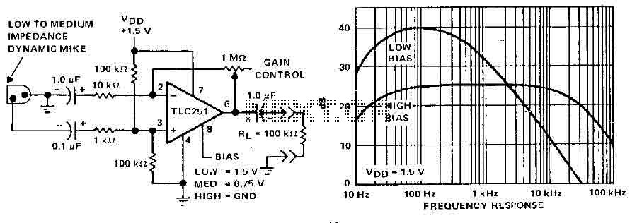
A microphone preamplifier utilizing a CMOS operational amplifier powered by its own battery is compact enough to fit within a small microphone casing. The amplifier functions with a 1.5V battery and exhibits low supply currents. This preamplifier operates at...
Many analog ohm meters have a non-linear scale, which results in poorer resolution at higher resistance values. This is due to the use of inexpensive current sources. Many analog ohm meters operate on a principle where the scale is not...
The Software Defined Radio (SDR) hardware, in its most basic configuration, includes a wideband switched balanced mixer and a low noise LF amplifier. This straightforward hardware demonstrates remarkable sensitivity and linearity, making it suitable for both testing and regular...
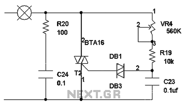
The TRIAC dimmer circuit diagram operates on the principle that a 220V lamp is controlled through the charging of capacitor C23 via resistors VR4 and R19. The charging time is influenced by the values of VR4 and R19, where...