
Complete Stand-Alone GPS Receiver Solution with MAX2742

This GPS solution integrates two critical components: the MAX2742 RF front-end receiver and the SONY CXD2932 GPS baseband processor. The MAX2742 is designed to operate in the GPS frequency range, providing high sensitivity and low power consumption. It features a low-noise amplifier (LNA) that amplifies weak GPS signals received from the antenna, ensuring that the signals are strong enough for processing. The RF front-end also includes a mixer and a voltage-controlled oscillator (VCO), which are essential for down-converting the RF signals to an intermediate frequency (IF) suitable for further processing.
The SONY CXD2932 serves as the GPS baseband processor, where it performs the necessary signal processing to extract the position data from the received signals. This component is equipped with advanced algorithms for satellite tracking, acquisition, and navigation calculations. It also includes a digital signal processor (DSP) that enhances the performance of the GPS system by improving signal accuracy and reducing the impact of interference.
Together, these components create a robust GPS solution that can be used in various applications, including automotive navigation systems, handheld GPS devices, and other location-based services. The integration of the MAX2742 and CXD2932 allows for a compact design, reducing the overall footprint of the GPS module while maintaining high performance. Additionally, the low power consumption of these components makes them suitable for battery-operated devices, extending the operational life of such systems. Overall, this complete GPS solution is characterized by its efficiency, accuracy, and versatility in real-world applications.Complete GPS solution using MAXIM CMOS RF front-end receiver MAX2742 and SONY GPS baseband CXD2932 is presented.. 🔗 External reference
Related Circuits
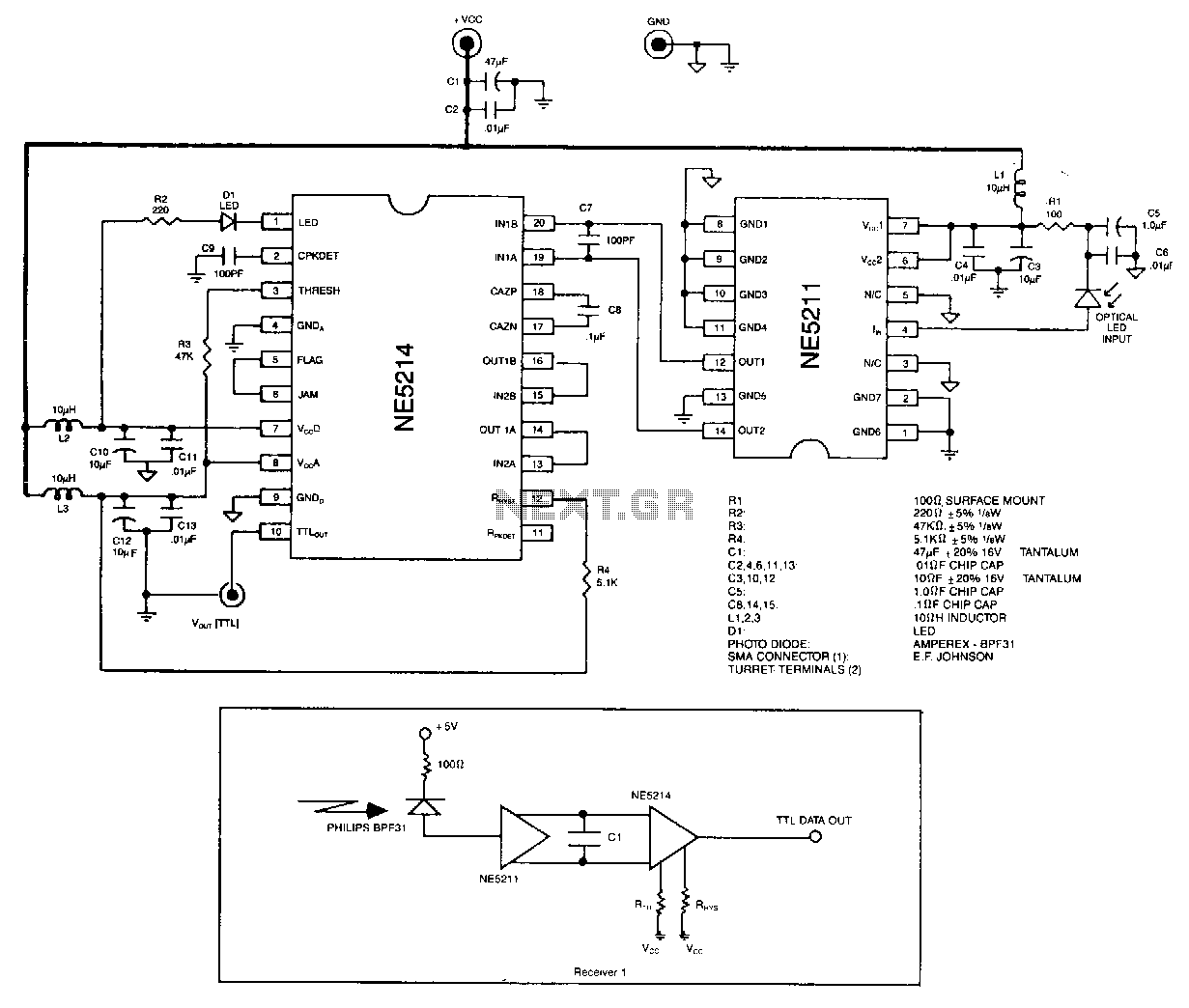
The optical signal is coupled to the pin diode. Current flowing in the diode also flows into the input of the NE5211 preamplifier. The preamplifier is a fixed-gain block that has a 28 kΩ differential transimpedance and performs a...
Frequency modulation (FM) can be used to transmit an analog voltage level signal with good noise immunity. The transmission itself might employ different techniques. Frequency modulation (FM) is a method widely utilized in communication systems to encode information in a...
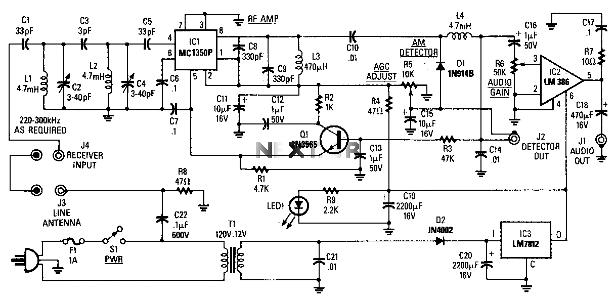
The AM Tuned Radio Frequency (TRF) receiver has a sensitivity of approximately 1 mV at the input for an audio output of 1/2 W. Capacitor C22 couples audio signals from the power line to the PC board and must...
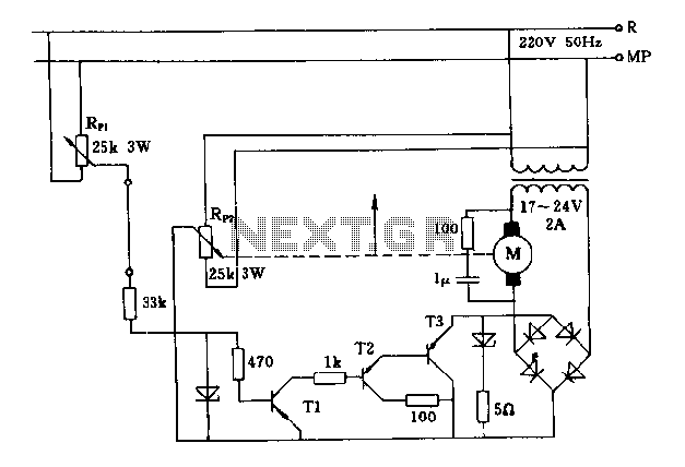
The FIG potentiometer RP2 has a sliding contact that is directly connected to the antenna. The system operates such that only when potentiometers RP1 and RP2 are positioned identically, do the non-conductive transistors and rectifier bridge remain off, resulting...
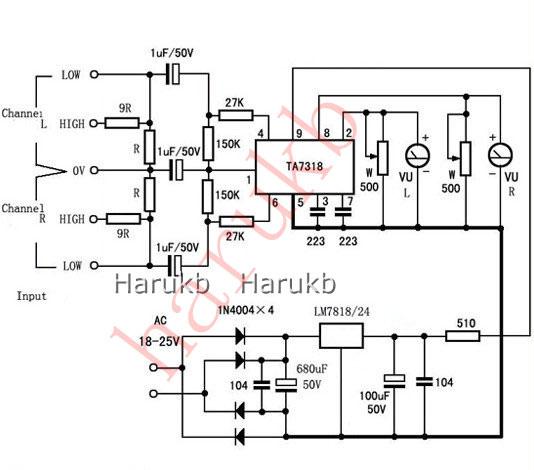
VU Meter Driver PCB Completed Board Stereo for Two VU Meters Audio Amplifier. VU Meter Driver PCB Completed TA7318P Board Stereo for Two VU Meters Features: Specifications: Power voltage: AC 20V to AC 26V (not more than 26V) size:...
A GPS receiver costing less than a few hundred dollars can provide immediate location information, including latitude, longitude, and altitude, accurate to within a few hundred feet. The output from the Voltage-Controlled Oscillator (VCO) is directly connected to a...