
Satellite receiver antenna servo control circuit diagram
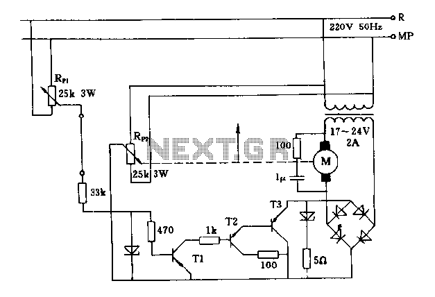
The described circuit involves a dual potentiometer setup, specifically RP1 and RP2, which are critical for controlling the position of an antenna through a motor. The sliding contact of potentiometer RP2 is mechanically linked to the antenna, allowing for direct positional feedback.
In this configuration, both potentiometers must be aligned to ensure that the system remains inactive, meaning that no power is supplied to the motor. This is achieved through the use of non-conductive transistors that are controlled by the voltage output from the potentiometers. The rectifier bridge plays a vital role in converting AC to DC voltage, but in this scenario, it remains off when the potentiometers are not in the same position.
When the potentiometers are not aligned, the system activates the motor, allowing the antenna to adjust its position in accordance with the reference set by the potentiometers. This synchronous rotation mechanism ensures that the antenna can follow the desired positional reference accurately. The design emphasizes the importance of maintaining alignment between the two potentiometers to prevent unintended movement of the antenna, which could lead to misalignment in applications such as radio frequency transmission or reception.
This circuit exemplifies a feedback control system where precise adjustments can be made based on the relative positions of the potentiometers, ensuring that the antenna remains in the optimal position for its intended function. The careful arrangement of components, including the potentiometers, transistors, and rectifier bridge, is crucial for the reliable operation of the system.FIG potentiometer RP2 sliding contact with the axle shaft is directly connected to the antenna. Only when given potentiometer RP1 and RP2 refers in the same position, only non- conductive transistors, rectifier bridge off, no voltage on the motor, the antenna stationary, otherwise the motor or antenna will follow the reference potentiometer synchronous rotation.
Related Circuits
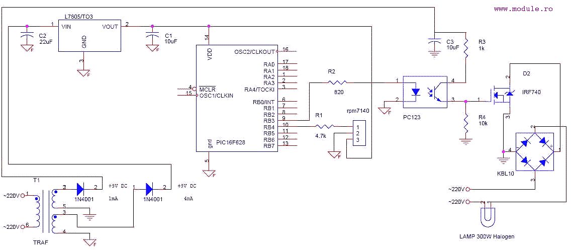
This is a simple schematic designed to control a lamp using a Sony TV remote control. The circuit employs a PWM signal connected to a photocoupler, which isolates the power section from the microcontroller. The power section features an...
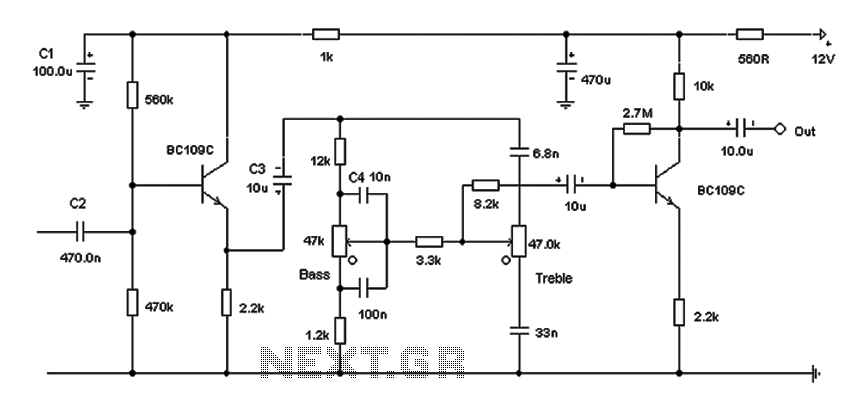
Based on the classic Baxendall tone control circuit, this design offers a maximum cut and boost of approximately 10 dB at 10 kHz and 50 Hz. Since the controls are passive, the final transistor provides a slight boost. The...
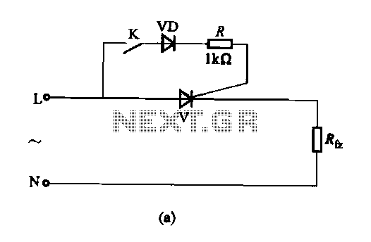
The thyristor AC switch circuit is not triggered, due to its simplicity, cost-effectiveness, and non-contact operation, making it widely utilized. The circuit is illustrated in Figure 16-43. It consists of single-phase thyristor switching circuits. Figure 16-43 (a) depicts a...
At half brightness, the lamp current is pulsed on and off by the voltage developed across the resistor and capacitor at the current-sense output. The current-sense output detects the lamp current. A basic pulse-width modulation (PWM) lamp-brightness control circuit...

Designed for Birkbeck, the microscope controller is an open-source stepper motor driver that utilizes an Arduino Uno and an Arduino stepper motor shield to operate a Phytron ZSS32 200 1.2A 3V stepper motor. The sample port movement is facilitated...

This circuit exhibits an exceptionally fast high-frequency response, as demonstrated by applying a 100 kHz square wave to the input. All graphs were produced using Tina Pro. The circuit's design is optimized for high-frequency applications, showcasing rapid response times that...