
Constant Current Source LED Drive

The constant current source LED driver circuit is designed to provide a stable current to an LED, ensuring its longevity and performance. The circuit primarily consists of two NPN transistors, resistors, and the LED itself. The upper NPN transistor acts as the main switch for the LED, while the lower NPN transistor serves as a feedback mechanism to regulate the current flowing through the LED.
The circuit operates as follows: when a voltage is applied through the 4.7kΩ resistor to the base of the upper NPN transistor, it turns on, allowing current to flow through the LED. The LED's forward voltage drop is typically around 1.7V for a green LED, and this voltage is taken into account when determining the resistor value. The current flowing through the LED is limited by the resistor, ensuring that it does not exceed the safe operating limits of the LED and the transistors.
In the absence of the lower NPN transistor, the upper NPN transistor would operate independently, and the current could potentially exceed the desired level, leading to damage. However, with the lower NPN in place, it monitors the current through the LED. As the LED current increases, the voltage across the resistor rises, eventually reaching the threshold voltage of 0.7V required to turn on the lower NPN transistor. Once activated, the lower NPN begins to draw current from the base of the upper NPN, reducing its bias and consequently lowering the LED current. This feedback mechanism ensures that the current remains within the desired range, providing a stable and reliable operation of the LED driver circuit.
The choice of transistors, such as the BC547, is critical for the performance of the circuit, as it must handle the expected current and voltage levels. The circuit should also be tested under various conditions to ensure that it operates effectively across the intended range of input voltages and load conditions. Proper thermal management and component selection are essential to prevent overheating and ensure long-term reliability of the LED driver.This is a Constant Current Source LED Driver, When the LED driver Upper-NPN is driven by a voltage thru 4. 7K the LED lights up. Assume that the Lower-NPN at bottom is absent. The current via LED and NPN is limited by R. 20mA may be ok 15mA even better. Or LED blows even transistor goes. BC547 is like 100mA-40V-200b, Limit collector current to 60mA , use it at less than 25V and depending on the individual transistor you may get a DC current amplification of 200 times. That is 1uA of base-emitter current could give a whooping 200uA of collector-emitter current. Still Thinking we do not have the Lower-NPN we calculate the resistor. Vcc ( 2 LEDs * 1. 7) Vce = Vr that is the voltage across the resistor. You know ohms law and the current needs to be 15mA for a bright and long lasting LED. Lastly 1. 7 the forward drop of a green LED and 0. 6 a saturated or Turrned-On NPN Vce. Now you use the Lower-NPN, The above calculations do not hold anymore. Let us think a small current is flowing in the LED. Then the voltage across R is less than 0. 7V, that means base-emitter diode of the Lower-NPN will not get to conduct. The Collector does not draw any current away. Now think that more current flows in LED, the voltage across R builds up above 0. 7V the Lower-NPN is biased. The collector of Lower-NPN starts drinking current from the base of the Upper-NPN. So The Upper-NPN starts losing its bias. This lowers the LED current and contains, regulates or controls the LED current as shown in the formula.
We aim to transmit more information by carrying articles. Please send us an E-mail to wanghuali@hqew. net within 15 days if we are involved in the problems of article content, copyright or other problems. We will delete it soon. 🔗 External reference
Related Circuits

LED lighting is becoming increasingly prominent in both residential and commercial lighting markets. To enhance the success and adoption of solid-state lighting in retrofit lamps, it is essential for LED lamps to support dimming with existing controllers and wiring....

The purpose of this circuit is to maintain a permanent magnet DC motor at a constant speed, which is set externally. This is achieved by monitoring the current flowing through and the voltage across the motor's brushes. The schematic for...
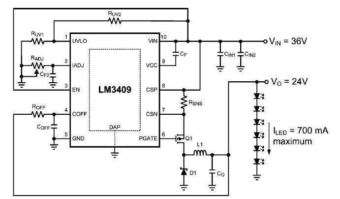
This dimming-controlled LED driver electronic circuit requires an input voltage of 36 volts and will provide an output voltage of 24 volts at a maximum current of 700 mA. The described dimming-controlled LED driver circuit is designed to efficiently convert...
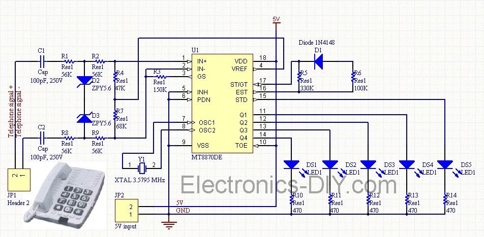
Cellphone Operated Land Rover (Mobile Phone Operated Robot). In this project, the robot is controlled by a mobile phone that makes a call to the mobile phone attached to the robot. The cellphone operated Land Rover project involves the design...
The consumer unit cupboard in some older houses is poorly illuminated. If a bell transformer is also situated in this cupboard, it can be utilized to provide emergency lighting using two high-current LEDs. These diodes are powered through a...
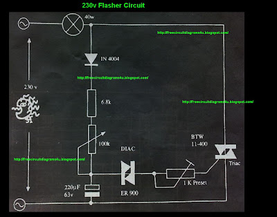
This circuit operates at 230V and can be utilized for party decoration purposes. It is sourced from an old circuit book titled "100 Circuit Book." The components include DIAC ER 900 and TRIAC BTW 11-400. The circuit is designed to...