
LM3409 dimming controlled LED driver circuit design

The described dimming-controlled LED driver circuit is designed to efficiently convert a higher input voltage of 36 volts down to a regulated output voltage of 24 volts, while allowing for a maximum output current of 700 mA. The circuit typically employs a buck converter topology, which is suitable for stepping down voltage levels while maintaining high efficiency.
Key components of the circuit include a switching device, such as a MOSFET, which is controlled by a pulse-width modulation (PWM) signal to adjust the output brightness of the LED. The PWM signal modulates the duty cycle, effectively controlling the average power delivered to the LED load. This dimming functionality is crucial for applications where varying light intensity is required.
Additionally, the circuit may incorporate feedback mechanisms to ensure stable operation and to maintain the output voltage at 24 volts under varying load conditions. A voltage reference and error amplifier are often utilized to compare the output voltage to the desired level, adjusting the PWM signal accordingly to minimize any deviations.
Inductors and capacitors are also integral to the design, providing energy storage and smoothing the output voltage, respectively. The inductor stores energy when the switch is closed and releases it to the output when the switch is open, while capacitors help filter out voltage ripples, ensuring a steady output.
Thermal management is another critical aspect of the design, as the components, particularly the switching device, can generate heat during operation. Adequate heat sinking or thermal pads may be employed to dissipate heat effectively, thus enhancing the reliability and longevity of the circuit.
Overall, this dimming-controlled LED driver circuit provides a versatile solution for various LED applications, allowing for efficient voltage conversion and adjustable brightness levels.This dimming controlled LED driver electronic circuit require an input voltage of 36 volts and will provide at output a voltage of 24 volts at a maximum current of 700mA 🔗 External reference
Related Circuits
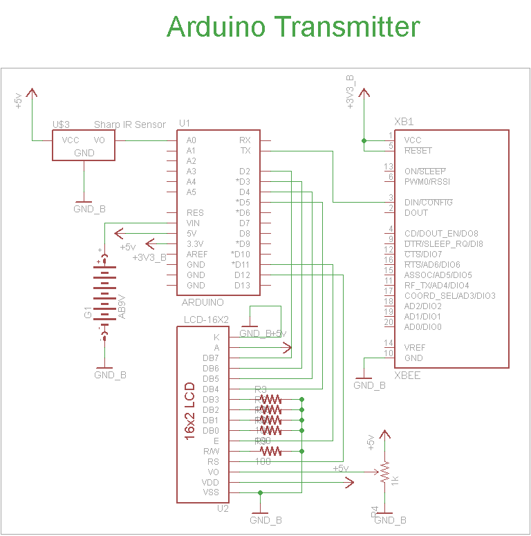
The schematic for the transmitter in this project consists of four main components: the Arduino UNO, the Sharp IR distance sensor, the XBee wireless modules, and a 16x2 LCD. The connections between these components are illustrated in the schematic....
This miniature audio amplifier provides an output of up to 250mW and can function as a final stage audio amplifier for radio sets. The schematic is straightforward, featuring one BC transistor. The described miniature audio amplifier is designed for efficient...
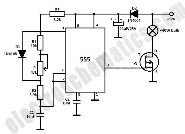
This light dimmer is designed to adjust the brightness of 12V light bulbs utilizing the widely recognized 555 timer, which is configured as an astable multivibrator. The pulses generated by the timer control the power delivered to the light...
The circuit comprises a 3-stage resistor-capacitor coupled amplifier. When ring button S2 is pressed, the amplifier circuit formed around transistors T1 and T2 gets converted into an asymmetrical astable multivibrator generating ring signals. These ring signals are amplified by...
Free domains and hosting with up to 1GB of disk space, unlimited transfer, and access to PHP as well as 5 MySQL databases. The maximum size of a single file is not limited. This service offers a robust web hosting...
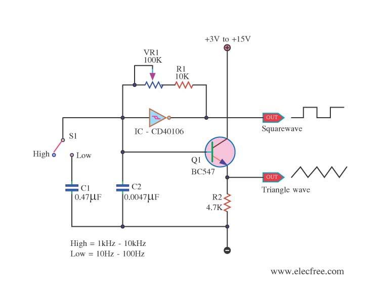
This is a function generator project that can be used as a triangle and square wave generator. The main components include the CD40106, a popular CMOS integrated circuit, and a standard transistor. The function generator circuit utilizes the CD40106, which...